Tag Archives: amp

2003 Toyota Celica Audio Radio Wiring Diagram Colors Schematic Headunit Install

Here is the audio stereo radio wiring information for your 2003 Toyota Celica with the standard or amplified systems. It will be useful when installing a stereo sound system, aftermarket headunit radio, or other automotive accessories. Make sure to grab the appropriate tools to test all the wires in your Celica. Please check it over and use it as a GUIDE only to help you locate the appropriate wires. This schematic is provided free of charge and may not be 100% accurate. Failure to properly test all the wires may lead to vehicle or bodily damage. All information is provided as-is and accuracy is not guaranteed.

2003 Toyota Celica Audio Radio Wiring Diagram Colors Schematic Headunit Install

If you find any conflicting info please leave a comment with what you found in your 2003 Toyota Celica. If you don’t see the audio radio wiring diagram you need comment and we will try to add it ASAP. Thanks for looking!

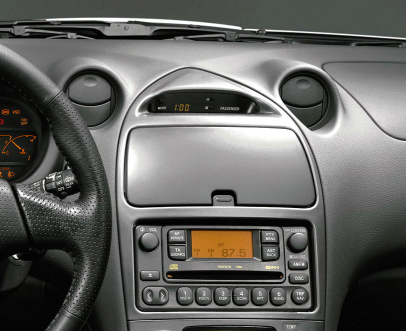
2003 Toyota Celica Audio Wiring Radio Diagram Schematic Colors – Aftermarket Stereo Installation Help

Car Radio Constant 12v+ Wire: Blue/Yellow @ Radio Harness
Car Stereo Ground Wire: Brown @ Radio Harness
Car Radio Ignition Switched Wire: Gray @ Radio Harness
Car Radio Illumination Wire: Green @ Radio Harness
Car Radio Dimmer Wire: N/A
Car Radio Amp Turn On Wire: Red (+) @ Radio Harness
Reverse Trigger: Red/Black @ Under Center Console Black 13-pin plug, pin 13
Car Stereo Power Antenna: N/A

Left Front Speaker Wire (+) Positive: Pink
Left Front Speaker Wire (-) Negative: Purple
Right Front Speaker Wire (+) Positive: Light Green
Right Front Speaker Wire (-) Negative: Blue

Left Rear Speaker Wire (+) Positive: Black
Left Rear Speaker Wire (-) Negative: Yellow
Right Rear Speaker Wire (+) Positive: Red
Right Rear Speaker Wire (-) Negative: White

SPEAKER WIRE COLORS AT THE AMP BEHIND/UNDER THE GLOVEBOX

Left Front Door Speaker Wire (+) Positive: White
Left Front Door Speaker Wire (-) Negative: Black

Right Front Door Speaker Wire (+) Positive: Red
Right Front Door Speaker Wire (-) Negative: Black

Left Rear Door Speaker Wire (+) Positive: Yellow
Left Rear Door Speaker Wire (-) Negative: Black

Right Rear Door Speaker Wire (+) Positive: Blue
Right Rear Door Speaker Wire (-) Negative: Black

Center Channel Speaker Wire Positive / Negative: N/A

Subwoofer Speaker Wire Positive / Negative: N/A

Radio Size: Single or Double Din

Radio Removal Tools: – Dash Removal Plastic Pry Tools – Use the pry tools to pop the gear shift trim bezel then remove 2 phillips screws below the climate controls. Pull off the climate control knobs and remove 2 phillips screws behind them. Unclip the climate control / radio trim bezel and remove. Remove 4 10mm bolts holding the factory radio in. Keep a magnet handy they are easy to drop!

Keep in mind if you are installing a new radio in your Celica you need the wiring harness, the antenna adapter, and the mounting kit as well.

REQUIRED PARTS FOR AFTERMARKET RADIO INSTALL

WIRING HARNESS WITH FACTORY AMP:

WIRING HARNESS WITHOUT FACTORY AMP:

MOUNTING KIT FOR SINGLE DIN AFTERMARKET RADIOS:

MOUNTING KIT FOR DOUBLE DIN AFTERMARKET RADIOS:

ANTENNA ADAPTER:

N/A

SPEAKER ADAPTERS FOR AFTERMARKET SPEAKER INSTALL:

If doing front and rear speakers order 2 of these!

RECOMMENDED TOOLS FOR THE INSTALL – SAME ONES THE PROS USE!

– 3M Electrical Tape

– Dash Removal Plastic Pry Tools

– Gardner Bender Auto Wire Stripper

– Klein Wire Cutters / Crimpers

– Install Bay Butt Connectors

2000 Toyota Celica Audio Radio Wiring Diagram Colors Schematic Install

Here is the audio stereo radio wiring information for your 2000 Toyota Celica with the standard or amplified systems. It will be useful when installing a stereo sound system, aftermarket headunit radio, or other automotive accessories. Make sure to grab the appropriate tools to test all the wires in your Celica. Please check it over and use it as a GUIDE only to help you locate the appropriate wires. This schematic is provided free of charge and may not be 100% accurate. Failure to properly test all the wires may lead to vehicle or bodily damage. All information is provided as-is and accuracy is not guaranteed.

2000 Toyota Celica Radio Audio Wiring Diagram Schematic Colors Install

If you find any conflicting info please leave a comment with what you found in your 2000 Toyota Celica. If you don’t see the audio radio wiring diagram you need comment and we will try to add it ASAP. Thanks for looking!

2000 Toyota Celica Audio Wiring Radio Diagram Schematic Colors – Aftermarket Stereo Installation Help

Car Radio Constant 12v+ Wire: Blue/Yellow @ Radio Harness
Car Stereo Ground Wire: Brown @ Radio Harness
Car Radio Ignition Switched Wire: Gray @ Radio Harness
Car Radio Illumination Wire: Green @ Radio Harness
Car Radio Dimmer Wire: N/A
Car Radio Amp Turn On Wire: Red (+) @ Radio Harness
Reverse Trigger: Red/Black @ Under Center Console Black 13-pin plug, pin 13
Car Stereo Power Antenna: N/A

Left Front Speaker Wire (+) Positive: Pink
Left Front Speaker Wire (-) Negative: Purple
Right Front Speaker Wire (+) Positive: Light Green
Right Front Speaker Wire (-) Negative: Blue

Left Rear Speaker Wire (+) Positive: Black
Left Rear Speaker Wire (-) Negative: Yellow
Right Rear Speaker Wire (+) Positive: Red
Right Rear Speaker Wire (-) Negative: White

SPEAKER WIRE COLORS AT THE AMP BEHIND/UNDER THE GLOVEBOX

Left Front Door Speaker Wire (+) Positive: White
Left Front Door Speaker Wire (-) Negative: Black

Right Front Door Speaker Wire (+) Positive: Red
Right Front Door Speaker Wire (-) Negative: Black

Left Rear Door Speaker Wire (+) Positive: Yellow
Left Rear Door Speaker Wire (-) Negative: Black

Right Rear Door Speaker Wire (+) Positive: Blue
Right Rear Door Speaker Wire (-) Negative: Black

Center Channel Speaker Wire Positive / Negative: N/A

Subwoofer Speaker Wire Positive / Negative: N/A

Radio Size: Single or Double Din

Radio Removal Tools: – Dash Removal Plastic Pry Tools – Use the pry tools to pop the gear shift trim bezel then remove 2 phillips screws below the climate controls. Pull off the climate control knobs and remove 2 phillips screws behind them. Unclip the climate control / radio trim bezel and remove. Remove 4 10mm bolts holding the factory radio in. Keep a magnet handy they are easy to drop!

Keep in mind if you are installing a new radio in your Celica you need the wiring harness, the antenna adapter, and the mounting kit as well.

REQUIRED PARTS FOR AFTERMARKET RADIO INSTALL

WIRING HARNESS WITHOUT FACTORY AMP:

WIRING HARNESS WITH FACTORY AMP:

MOUNTING KIT FOR SINGLE DIN AFTERMARKET RADIOS:

MOUNTING KIT FOR DOUBLE DIN AFTERMARKET RADIOS:

ANTENNA ADAPTER:

N/A

SPEAKER ADAPTERS FOR AFTERMARKET SPEAKER INSTALL:

If doing front and rear speakers order 2!

RECOMMENDED TOOLS FOR THE INSTALL – SAME ONES THE PROS USE!

– 3M Electrical Tape

– Klein Wire Cutters / Crimpers

– Install Bay Butt Connectors

– Dash Removal Plastic Pry Tools

– Gardner Bender Auto Wire Stripper

2001 Toyota Celica Radio Audio Wiring Diagram Schematic Colors Install

Here is the audio stereo radio wiring information for your 2001 Toyota Celica with the standard or amplified systems. It will be useful when installing an aftermarket headunit radio, sound stereo system, or other automotive accessories. Make sure to grab the appropriate tools to test all the wires in your Celica. Please check it over and use it as a GUIDE only to help you locate the appropriate wires. This schematic is provided free of charge and may not be 100% accurate. Failure to properly test all the wires may lead to vehicle or bodily damage. All information is provided as-is and accuracy is not guaranteed.

2001 Toyota Celica Radio Audio Wiring Diagram Schematic Colors Install
2001 Toyota Celica Radio Audio Schematic Colors Install Wiring Diagram

If you find any conflicting info please leave a comment with what you found in your 2001 Toyota Celica. If you don’t see the audio radio wiring diagram you need comment and we will try to add it ASAP. Thanks for looking!

2001 Toyota Celica Audio Wiring Radio Diagram Schematic Colors – Aftermarket Stereo Installation Help

Car Radio Constant 12v+ Wire: Blue/Yellow @ Radio Harness
Car Stereo Ground Wire: Brown @ Radio Harness
Car Radio Ignition Switched Wire: Gray @ Radio Harness
Car Radio Illumination Wire: Green @ Radio Harness
Car Radio Dimmer Wire: N/A
Car Radio Amp Turn On Wire: Red (+) @ Radio Harness
Reverse Trigger: Red/Black @ Under Center Console Black 13-pin plug, pin 13
Car Stereo Power Antenna: N/A
Left Front Speaker Wire (+) Positive: Pink
Left Front Speaker Wire (-) Negative: Purple
Right Front Speaker Wire (+) Positive: Light Green
Right Front Speaker Wire (-) Negative: Blue

Left Rear Speaker Wire (+) Positive: Black
Left Rear Speaker Wire (-) Negative: Yellow
Right Rear Speaker Wire (+) Positive: Red
Right Rear Speaker Wire (-) Negative: White

SPEAKER WIRE COLORS AT THE AMP BEHIND/UNDER THE GLOVEBOX

Left Front Door Speaker Wire (+) Positive: White
Left Front Door Speaker Wire (-) Negative: Black

Right Front Door Speaker Wire (+) Positive: Red
Right Front Door Speaker Wire (-) Negative: Black

Left Rear Door Speaker Wire (+) Positive: Yellow
Left Rear Door Speaker Wire (-) Negative: Black

Right Rear Door Speaker Wire (+) Positive: Blue
Right Rear Door Speaker Wire (-) Negative: Black

Center Channel Speaker Wire Positive / Negative: N/A

Subwoofer Speaker Wire Positive / Negative: N/A

Radio Size: Single or Double Din

Radio Removal Tools: – Dash Removal Plastic Pry Tools – Use the pry tools to pop the gear shift trim bezel then remove 2 phillips screws below the climate controls. Pull off the climate control knobs and remove 2 phillips screws behind them. Unclip the climate control / radio trim bezel and remove. Remove 4 10mm bolts holding the factory radio in. Keep a magnet handy they are easy to drop!

Keep in mind if you are installing a new radio in your Celica you need the wiring harness, the antenna adapter, and the mounting kit as well.

REQUIRED PARTS FOR AFTERMARKET RADIO INSTALL

WIRING HARNESS WITHOUT FACTORY AMP:

WIRING HARNESS WITH FACTORY AMP:

MOUNTING KIT FOR DOUBLE DIN AFTERMARKET RADIOS:

MOUNTING KIT FOR SINGLE DIN AFTERMARKET RADIOS:

ANTENNA ADAPTER:

N/A

SPEAKER ADAPTERS FOR AFTERMARKET SPEAKER INSTALL:

If doing front and rear speakers order 2!

RECOMMENDED TOOLS FOR THE INSTALL – SAME ONES THE PROS USE!

– 3M Electrical Tape

– Klein Wire Cutters / Crimpers

– Install Bay Butt Connectors

– Gardner Bender Auto Wire Stripper

– Dash Removal Plastic Pry Tools

2002 Toyota Celica Radio Audio Wiring Diagram Schematic Colors Install

Here is the stereo radio wiring information for your 2002 Toyota Celica with the standard or amplified systems. It will be useful when installing an aftermarket headunit radio, sound stereo system, or other automotive accessories. Make sure to grab the appropriate tools to test all the wires in your Celica. Please check it over and use it as a GUIDE to help you locate the appropriate wires. This schematic is provided free of charge and may not be 100% accurate. Failure to properly test all the wires may lead to vehicle or bodily damage. All information is provided as-is and accuracy is not guaranteed.

2002 Toyota Celica Radio Audio Wiring Diagram Schematic Colors Install

If you find any conflicting info please leave a comment with what you found in your 2002 Toyota Celica. If you don’t see the audio radio wiring diagram you need comment and we will try to add it ASAP. Thanks for looking!

2002 Toyota Celica Audio Wiring Radio Diagram Schematic Colors – Aftermarket Stereo Installation Help

Car Radio Constant 12v+ Wire: Blue/Yellow @ Radio Harness
Car Stereo Ground Wire: Brown @ Radio Harness
Car Radio Ignition Switched Wire: Gray @ Radio Harness
Car Radio Illumination Wire: Green @ Radio Harness
Car Radio Dimmer Wire: N/A
Car Stereo Power Antenna: N/A
Car Radio Amp Turn On Wire: Red (+) @ Radio Harness
Reverse Trigger: Red/Black @ Under Center Console Black 13-pin plug, pin 13
Left Front Speaker Wire (+) Positive: Pink
Left Front Speaker Wire (-) Negative: Purple
Right Front Speaker Wire (+) Positive: Light Green
Right Front Speaker Wire (-) Negative: Blue

Left Rear Speaker Wire (+) Positive: Black
Left Rear Speaker Wire (-) Negative: Yellow
Right Rear Speaker Wire (+) Positive: Red
Right Rear Speaker Wire (-) Negative: White

SPEAKER WIRE COLORS AT THE AMP BEHIND/UNDER THE GLOVEBOX

Left Front Door Speaker Wire (+) Positive: White
Left Front Door Speaker Wire (-) Negative: Black

Right Front Door Speaker Wire (+) Positive: Red
Right Front Door Speaker Wire (-) Negative: Black

Left Rear Door Speaker Wire (+) Positive: Yellow
Left Rear Door Speaker Wire (-) Negative: Black

Right Rear Door Speaker Wire (+) Positive: Blue
Right Rear Door Speaker Wire (-) Negative: Black

Center Channel Speaker Wire Positive / Negative: N/A

Subwoofer Speaker Wire Positive / Negative: N/A

Radio Size: Single or Double Din

Radio Removal Tools: – Dash Removal Plastic Pry Tools – Use the pry tools to pop the gear shift trim bezel then remove 2 phillips screws below the climate controls. Pull off the climate control knobs and remove 2 phillips screws behind them. Unclip the climate control / radio trim bezel and remove. Remove 4 10mm bolts holding the factory radio in. Keep a magnet handy they are easy to drop!

Keep in mind if you are installing a new radio in your Celica you need the wiring harness, the antenna adapter, and the mounting kit as well.

REQUIRED PARTS FOR AFTERMARKET RADIO INSTALL

WIRING HARNESS WITHOUT FACTORY AMP:

WIRING HARNESS WITH FACTORY AMP:

MOUNTING KIT FOR DOUBLE DIN AFTERMARKET RADIOS:

MOUNTING KIT FOR SINGLE DIN AFTERMARKET RADIOS:

ANTENNA ADAPTER:

N/A

SPEAKER ADAPTERS FOR AFTERMARKET SPEAKER INSTALL:

If doing front and rear speakers order 2!

RECOMMENDED TOOLS FOR THE INSTALL – SAME ONES THE PROS USE!

– 3M Electrical Tape

– Install Bay Butt Connectors

– Klein Wire Cutters / Crimpers

– Gardner Bender Auto Wire Stripper

– Dash Removal Plastic Pry Tools

2014 Mitsubishi Mirage Radio Audio Wiring Diagram Schematic Colors Install

Here is the stereo radio wiring information for your 2014 Mitsubishi Mirage body with the standard or amplified systems. It will be useful when installing an aftermarket headunit radio, sound stereo system, or other automotive accessories. Make sure to grab the appropriate tools to test all the wires in your Mirage. Please check it over and use it as a GUIDE to help you locate the appropriate wires. This schematic is provided free of charge and may not be 100% accurate. Failure to properly test all the wires may lead to vehicle or bodily damage. All information is provided as-is and accuracy is not guaranteed.

2014 Mitsubishi Mirage Car Audio Wiring Diagram

If you find any conflicting info please leave a comment with what you found in your 2014 Mitsubishi Mirage. If you don’t see the audio radio wiring diagram you need comment and we will try to add it ASAP. Thanks for looking!

2014 Mitsubishi Mirage Audio Wiring Radio Diagram Schematic Colors – Aftermarket Stereo Installation Help

Car Radio Constant 12v+ Wire: White @ Pin 10 Radio Harness
Car Stereo Ground Wire: Black @ Pin 20 Radio Harness
Car Radio Ignition Switched Wire: Blue @ Pin 1 Radio Harness
Car Radio Illumination Wire: Gray @ Radio Harness
Car Radio Dimmer Wire: Light Blue @ Radio Harness
Car Stereo Power Antenna: N/A
Car Radio Amp Turn On Wire: N/A
Reverse Trigger: Dark Blue – Pin 7 @ Main Radio Harness

Left Front Speaker Wire (+) Positive: Red
Left Front Speaker Wire (-) Negative: Green
Right Front Speaker Wire (+) Positive: Brown
Right Front Speaker Wire (-) Negative: Purple

Left Rear Speaker Wire (+) Positive: Green
Left Rear Speaker Wire (-) Negative: White
Right Rear Speaker Wire (+) Positive: Brown
Right Rear Speaker Wire (-) Negative: Gray

SPEAKER WIRE COLORS AT THE SPEAKERS IN THE DOORS

Left Front Door Speaker Wire (+) Positive: Red
Left Front Door Speaker Wire (-) Negative: Yellow

Right Front Door Speaker Wire (+) Positive: Red
Right Front Door Speaker Wire (-) Negative: Blue

Left Rear Door Speaker Wire (+) Positive: Gray
Left Rear Door Speaker Wire (-) Negative: Light Blue

Right Rear Door Speaker Wire (+) Positive: Gray
Right Rear Door Speaker Wire (-) Negative: Light Blue

Center Channel Speaker Wire Positive / Negative: N/A

Subwoofer Speaker Wire Positive / Negative: N/A

Radio Size: Single or Double Din

Radio Removal Tools: – Dash Removal Plastic Pry Tools – Without OEM Nav: Use the pry tools to remove the vents above the radio. After that use a Phillips screwdriver the radio is held in with 2 screws. WITH OEM NAV: Use the pry tools to remove the vents and radio panel. After that use a Phillips screwdriver the radio is held in with 4 screws.

Keep in mind if you are installing a new radio in your Mirage you need the wiring harness, the antenna adapter, steering wheel control module, and the mounting kit as well.

REQUIRED PARTS FOR AFTERMARKET RADIO INSTALL

WIRING HARNESS:

WITHOUT OEM NAVIGATION: MOUNTING KIT FOR DOUBLE DIN AFTERMARKET RADIOS:

WITHOUT OEM NAVIGATION: MOUNTING KIT FOR SINGLE DIN AFTERMARKET RADIOS:

WITH OEM NAVIGATION: MOUNTING KIT FOR DOUBLE DIN AFTERMARKET RADIOS:

Use the OEM brackets attached to the factory nav unit along with the kit below to fill the gaps on the sides:

ANTENNA ADAPTER:

N/A

STEERING WHEEL CONTROLS ADAPTER:

Metra Axxess ASWC-1 Universal Steering Wheel Control Interface

ASWC-1 Installation Instructions:

Connect the red wire to the red switched lead from your aftermarket radio.

Connect the black wire to the black ground lead from your aftermarket radio.

Connect the black/green from the ASWC-1 to the pink wire in pin 9 or 2 depending which end you count from in the main radio connector.

Ground the purple wire in pin 19 or 11 depending which end you count from in the main radio connector.

AS of April 2015 the module will not auto detect you will have to follow the instructions to manually program but it works great after that!

FACTORY BACKUP REVERSE CAMERA INTEGRATION:

If you want the OEM camera to display on your aftermarket navigation, it runs off of 6v so you will need the below 5v adapter and a female adapter to hardwire it behind the radio. The camera wires are in a 5-pin plug behind the radio. For camera power you want to supply 6v from the adapters below to the purple wire and then ground the light blue and red wires.

For the video signal itself grab a bulk rca video cable below and cut it in half. Strip the ends and you’ll have the center conductor and shield. Connect the center conductor to the video positive which is black in the 5-pin plug. Connect the shield to the gray wire in the 5-pin plug.

RECOMMENDED TOOLS FOR THE INSTALL – SAME ONES THE PROS USE!

– 3M Electrical Tape

– Install Bay Butt Connectors

– Klein Wire Cutters / Crimpers

– Gardner Bender Auto Wire Stripper

– Dash Removal Plastic Pry Tools

2015 Mitsubishi Mirage Radio Audio Wiring Diagram Schematic Colors Install

Here is the stereo radio wiring information for your 2015 Mitsubishi Mirage body with the standard or amplified systems. It will be useful when installing an aftermarket radio, sound stereo system, or other automotive accessories. Make sure to grab the appropriate tools to test all the wires in your Mirage. Please check it over and use it as a GUIDE to help you locate the appropriate wires. This schematic is provided free of charge and may not be 100% accurate. Failure to properly test all the wires may lead to vehicle or bodily damage. All information is provided as-is and accuracy is not guaranteed.

2015 Mitsubishi Mirage Car Audio Aftermarket Install Diagram

If you find any conflicting info please leave a comment with what you found in your Mitsubishi Mirage. If you don’t see the audio radio wiring diagram you need comment and we will try to add it ASAP. Thanks for looking!

2015 Mitsubishi Mirage Audio Wiring Radio Diagram Schematic Colors – Aftermarket Stereo Installation Help

Car Radio Constant 12v+ Wire: White @ Pin 10 Radio Harness
Car Stereo Ground Wire: Black @ Pin 20 Radio Harness
Car Radio Ignition Switched Wire: Blue @ Pin 1 Radio Harness
Car Radio Illumination Wire: Gray @ Radio Harness
Car Radio Dimmer Wire: Light Blue @ Radio Harness
Car Stereo Power Antenna: N/A
Car Radio Amp Turn On Wire: N/A
Reverse Trigger: Dark Blue – Pin 7 @ Main Radio Harness

Left Front Speaker Wire (+) Positive: Red
Left Front Speaker Wire (-) Negative: Green
Right Front Speaker Wire (+) Positive: Brown
Right Front Speaker Wire (-) Negative: Purple

Left Rear Speaker Wire (+) Positive: Green
Left Rear Speaker Wire (-) Negative: White
Right Rear Speaker Wire (+) Positive: Brown
Right Rear Speaker Wire (-) Negative: Gray

SPEAKER WIRE COLORS AT THE SPEAKERS IN THE DOORS

Left Front Door Speaker Wire (+) Positive: Red
Left Front Door Speaker Wire (-) Negative: Yellow

Right Front Door Speaker Wire (+) Positive: Red
Right Front Door Speaker Wire (-) Negative: Blue

Left Rear Door Speaker Wire (+) Positive: Gray
Left Rear Door Speaker Wire (-) Negative: Light Blue

Right Rear Door Speaker Wire (+) Positive: Gray
Right Rear Door Speaker Wire (-) Negative: Light Blue

Center Channel Speaker Wire Positive / Negative: N/A

Subwoofer Speaker Wire Positive / Negative: N/A

Radio Size: Single or Double Din

Radio Removal Tools: – Dash Removal Plastic Pry Tools – Without OEM Nav: Use the pry tools to remove the vents above the radio. After that use a Phillips screwdriver the radio is held in with 2 screws. WITH OEM NAV: Use the pry tools to remove the vents and radio panel. After that use a Phillips screwdriver the radio is held in with 4 screws.

Keep in mind if you are installing a new radio in your Mirage you need the wiring harness, the antenna adapter, steering wheel control module, and the mounting kit as well.

REQUIRED PARTS FOR AFTERMARKET RADIO INSTALL

WIRING HARNESS:

WITHOUT OEM NAVIGATION: MOUNTING KIT FOR DOUBLE DIN AFTERMARKET RADIOS:

WITHOUT OEM NAVIGATION: MOUNTING KIT FOR SINGLE DIN AFTERMARKET RADIOS:

WITH OEM NAVIGATION: MOUNTING KIT FOR DOUBLE DIN AFTERMARKET RADIOS:

Use the OEM brackets attached to the factory nav unit along with the kit below to fill the gaps on the sides:

ANTENNA ADAPTER:

N/A

STEERING WHEEL CONTROLS ADAPTER:

Metra Axxess ASWC-1 Universal Steering Wheel Control Interface

ASWC-1 Installation Instructions:

Connect the red wire to the red switched lead from your aftermarket radio.

Connect the black wire to the black ground lead from your aftermarket radio.

Connect the black/green from the ASWC-1 to the pink wire in pin 9 or 2 depending which end you count from in the main radio connector.

Ground the purple wire in pin 19 or 11 depending which end you count from in the main radio connector.

AS of April 2015 the module will not auto detect you will have to follow the instructions to manually program but it works great after that!

FACTORY BACKUP REVERSE CAMERA INTEGRATION:

If you want the OEM camera to display on your aftermarket navigation, it runs off of 6v so you will need the below 5v adapter and a female adapter to hardwire it behind the radio. The camera wires are in a 5-pin plug behind the radio. For camera power you want to supply 6v from the adapters below to the purple wire and then ground the light blue and red wires.

For the video signal itself grab a bulk rca video cable below and cut it in half. Strip the ends and you’ll have the center conductor and shield. Connect the center conductor to the video positive which is black in the 5-pin plug. Connect the shield to the gray wire in the 5-pin plug.

SPEAKER WIRING ADAPTERS:

N/A

RECOMMENDED TOOLS FOR THE INSTALL – SAME ONES THE PROS USE!

– 3M Electrical Tape

– Install Bay Butt Connectors

– Gardner Bender Auto Wire Stripper

– Klein Wire Cutters / Crimpers

– Dash Removal Plastic Pry Tools

2009 Dodge Caliber Radio Audio Wiring Diagram Schematic Colors Install

Here is the stereo radio wiring information for your 2009 Dodge Caliber body with the standard or amplified systems. It will be useful when installing an aftermarket radio, sound stereo system, or other automotive accessories. Make sure to grab the appropriate tools to test all the wires in your Caliber. Please check it over and use it as a GUIDE to help you locate the appropriate wires. This schematic is provided free of charge and may not be 100% accurate. Failure to properly test all the wires may lead to vehicle or bodily damage. All information is provided as-is and accuracy is not guaranteed.

Dodge Caliber Audio Radio Wiring Diagram Schematic
2009 Dodge Caliber Audio Radio Wiring Diagram Schematic

If you find any conflicting info please leave a comment with what you found in your Dodge Caliber. If you don’t see the audio radio wiring diagram you need comment and we will try to add it ASAP. Thanks for looking!

2009 Dodge Caliber Audio Wiring Radio Diagram Schematic Colors – Aftermarket Stereo Installation Help

Car Radio Constant 12v+ Wire: Red/Light Blue
Car Stereo Ground Wire: Black/Yellow or Black/Green
Car Radio Ignition Switched Wire: @ Cigarette Lighter Below Radio
Car Radio Illumination Wire: White/Purple @ Drivers kick panel harness
Car Stereo Power Antenna: Gray/Red (+) @ Radio Harness
Car Radio Amp Turn On Wire:

Left Front Speaker Wire (+) Positive: Gray/Purple
Left Front Speaker Wire (-) Negative: Gray/Yellow
Right Front Speaker Wire (+) Positive: Green/Purple
Right Front Speaker Wire (-) Negative: Green/Yellow

Left Rear Speaker Wire (+) Positive: Green/Dark Blue
Left Rear Speaker Wire (-) Negative: Green/Brown
Right Rear Speaker Wire (+) Positive: Gray/Dark Blue
Right Rear Speaker Wire (-) Negative: Gray/Orange

SPEAKER WIRE COLORS AT THE SPEAKERS IN THE DOORS

Left Front Door Speaker Wire (+) Positive:
Left Front Door Speaker Wire (-) Negative:

Right Front Door Speaker Wire (+) Positive:
Right Front Door Speaker Wire (-) Negative:

Left Rear Door Speaker Wire (+) Positive:
Left Rear Door Speaker Wire (-) Negative:

Right Rear Door Speaker Wire (+) Positive:
Right Rear Door Speaker Wire (-) Negative:

Center Channel Speaker Wire Positive / Negative: N/A

Subwoofer Speaker Wire Positive / Negative: N/A

Radio Size: Single or Double Din

Radio Removal Tools:

Keep in mind if you are installing a new radio in your Caliber you need the wiring harness, the antenna adapter, steering wheel control module, and the mounting kit as well.

REQUIRED PARTS FOR AFTERMARKET RADIO INSTALL

BASE SYSTEM WIRING HARNESS:

MOUNTING KIT FOR DOUBLE DIN AFTERMARKET RADIOS:

(This kit can be used with double or single din radios! Vehicle MUST have OEM navigation to use this kit OR you will also need to purchase the OEM Nav Bezel
.

MOUNTING KIT FOR SINGLE DIN AFTERMARKET RADIOS:

(This kit can be used ONLY with single din radios! Vehicle must NOT have OEM navigation.

ANTENNA ADAPTER:

STEERING WHEEL CONTROLS ADAPTER:

Metra Axxess ASWC-1 Universal Steering Wheel Control Interface

SPEAKER WIRING ADAPTERS:

Use these when replacing the OEM speakers if you don’t want to cut or splice the OEM harness. Comes with 1 pair if doing all 4 speakers you will need to order 2.

RECOMMENDED TOOLS FOR THE INSTALL – SAME ONES THE PROS USE!

– 3M Electrical Tape

– Install Bay Butt Connectors

– Gardner Bender Auto Wire Stripper

– Klein Wire Cutters / Crimpers

– Dash Removal Plastic Pry Tools

2008 Dodge Caliber Radio Audio Wiring Diagram Schematic Colors

Here is the stereo radio wiring information for your 2008 Dodge Caliber body with the standard or amplified systems. It will be useful when installing an aftermarket radio, sound stereo system, or other automotive accessories. Make sure to grab the appropriate tools to test all the wires in your Caliber. Please check it over and use it as a GUIDE to help you locate the appropriate wires. This schematic is provided free of charge and may not be 100% accurate. Failure to properly test all the wires may lead to vehicle or bodily damage. All information is provided as-is and accuracy is not guaranteed.

Dodge Caliber Audio Radio Wiring Diagram Schematic
2008 Dodge Caliber Audio Radio Wiring Diagram Schematic

If you find any conflicting info please leave a comment with what you found in your Dodge Caliber. If you don’t see the audio radio wiring diagram you need comment and we will try to add it ASAP. Thanks for looking!

2008 Dodge Caliber Audio Wiring Radio Diagram Schematic Colors – Aftermarket Installation Help

Car Radio Constant 12v+ Wire: Red/Light Blue
Car Stereo Ground Wire: Black/Yellow or Black/Green
Car Radio Ignition Switched Wire: @ Cigarette Lighter Below Radio
Car Radio Illumination Wire: White/Purple @ Drivers kick panel harness
Car Stereo Power Antenna: Gray/Red (+) @ Radio Harness
Car Radio Amp Turn On Wire:

Left Front Speaker Wire (+) Positive: Gray/Purple
Left Front Speaker Wire (-) Negative: Gray/Yellow
Right Front Speaker Wire (+) Positive: Green/Purple
Right Front Speaker Wire (-) Negative: Green/Yellow

Left Rear Speaker Wire (+) Positive: Green/Dark Blue
Left Rear Speaker Wire (-) Negative: Green/Brown
Right Rear Speaker Wire (+) Positive: Gray/Dark Blue
Right Rear Speaker Wire (-) Negative: Gray/Orange

SPEAKER WIRE COLORS AT THE SPEAKERS IN THE DOORS

Left Front Door Speaker Wire (+) Positive:
Left Front Door Speaker Wire (-) Negative:

Right Front Door Speaker Wire (+) Positive:
Right Front Door Speaker Wire (-) Negative:

Left Rear Door Speaker Wire (+) Positive:
Left Rear Door Speaker Wire (-) Negative:

Right Rear Door Speaker Wire (+) Positive:
Right Rear Door Speaker Wire (-) Negative:

Center Channel Speaker Wire Positive / Negative: N/A

Subwoofer Speaker Wire Positive / Negative: N/A

Radio Size: Single or Double Din

Radio Removal Tools:

Keep in mind if you are installing a new radio you need the wiring harness, the antenna adapter, steering wheel control module, and the mounting kit as well.

REQUIRED PARTS FOR AFTERMARKET RADIO INSTALL

AMPLIFIED SYSTEM WIRING HARNESS:

BASE SYSTEM WIRING HARNESS:

MOUNTING KIT FOR DOUBLE DIN AFTERMARKET RADIOS:

(This kit can be used with double or single din radios! Vehicle MUST have OEM navigation to use this kit OR you will also need to purchase the OEM Nav Bezel
.

MOUNTING KIT FOR SINGLE DIN AFTERMARKET RADIOS:

(This kit can be used ONLY with single din radios! Vehicle must NOT have OEM navigation.

ANTENNA ADAPTER:

STEERING WHEEL CONTROLS ADAPTER:

Metra Axxess ASWC-1 Universal Steering Wheel Control Interface

SPEAKER WIRING ADAPTERS:

Use these when replacing the OEM speakers if you don’t want to cut or splice the OEM harness. Comes with 1 pair if doing all 4 speakers you will need to order 2.

RECOMMENDED TOOLS FOR THE INSTALL – SAME ONES THE PROS USE!

– 3M Electrical Tape

– Install Bay Butt Connectors

– Klein Wire Cutters / Crimpers

– Gardner Bender Auto Wire Stripper

– Dash Removal Plastic Pry Tools

2007 Dodge Caliber Radio Audio Wiring Diagram Schematic Colors

Here is the stereo radio wiring information for your 2007 Dodge Caliber body with the standard or amplified systems. It will be useful when installing an aftermarket radio, sound stereo system, or other automotive accessories. Make sure to grab the appropriate tools to test all the wires in your Caliber. Please check it over and use it as a GUIDE to help you locate the appropriate wires. This schematic is provided free of charge and may not be 100% accurate. Failure to properly test all the wires may lead to vehicle or bodily damage. All information is provided as-is and accuracy is not guaranteed.

Dodge Caliber Audio Radio Wiring Diagram Schematic

If you find any conflicting info please leave a comment with what you found in your Dodge Caliber. If you don’t see the audio radio wiring diagram you need comment and we will try to add it ASAP. Thanks for looking!

2007 Dodge Caliber Audio Wiring Radio Diagram Schematic Colors

Car Radio Constant 12v+ Wire: Red/Light Blue
Car Stereo Ground Wire: Black/Yellow or Black/Green
Car Radio Ignition Switched Wire: @ Cigarette Lighter Below Radio
Car Radio Illumination Wire: White/Purple @ Drivers kick panel harness
Car Stereo Power Antenna: Gray/Red (+) @ Radio Harness
Car Radio Amp Turn On Wire:

Left Front Speaker Wire (+) Positive: Gray/Purple
Left Front Speaker Wire (-) Negative: Gray/Yellow
Right Front Speaker Wire (+) Positive: Green/Purple
Right Front Speaker Wire (-) Negative: Green/Yellow

Left Rear Speaker Wire (+) Positive: Green/Dark Blue
Left Rear Speaker Wire (-) Negative: Green/Brown
Right Rear Speaker Wire (+) Positive: Gray/Dark Blue
Right Rear Speaker Wire (-) Negative: Gray/Orange

SPEAKER WIRE COLORS AT THE SPEAKERS IN THE DOORS

Left Front Door Speaker Wire (+) Positive:
Left Front Door Speaker Wire (-) Negative:
Right Front Door Speaker Wire (+) Positive:
Right Front Door Speaker Wire (-) Negative:

Left Rear Door Speaker Wire (+) Positive:
Left Rear Door Speaker Wire (-) Negative:
Right Rear Door Speaker Wire (+) Positive:
Right Rear Door Speaker Wire (-) Negative:

Center Channel Speaker Wire Positive / Negative: N/A

Subwoofer Speaker Wire Positive / Negative: N/A

Radio Size: Single or Double Din

Radio Removal Tools:

Keep in mind if you are installing a new radio you need the wiring harness, the antenna adapter, steering wheel control module, and the mounting kit as well.

REQUIRED PARTS FOR AFTERMARKET RADIO INSTALL

BASE SYSTEM WIRING HARNESS:

AMPLIFIED SYSTEM WIRING HARNESS:

MOUNTING KIT FOR DOUBLE DIN AFTERMARKET RADIOS:

(This kit can be used with double or single din radios! Vehicle MUST have OEM navigation to use this kit OR you will also need to purchase the OEM Nav Bezel
.

MOUNTING KIT FOR SINGLE DIN AFTERMARKET RADIOS:

(This kit can be used ONLY with single din radios! Vehicle must NOT have OEM navigation.

ANTENNA ADAPTER:

STEERING WHEEL CONTROLS ADAPTER:

Metra Axxess ASWC-1 Universal Steering Wheel Control Interface

SPEAKER WIRING ADAPTERS:

Use these when replacing the OEM speakers if you don’t want to cut or splice the OEM harness. Comes with 1 pair if doing all 4 speakers you will need to order 2.

RECOMMENDED TOOLS FOR THE INSTALL – SAME ONES THE PROS USE!

– 3M Electrical Tape

– Install Bay Butt Connectors

– Klein Wire Cutters / Crimpers

– Gardner Bender Auto Wire Stripper

– Dash Removal Plastic Pry Tools

2002 Mercedes Benz MB W203 C230 Kompressor Radio Audio Wiring Diagram Schematic Colors

Here is the stereo radio wiring information for your 2002 MB C230 W203 Kompressor body with the standard or amplified systems. It will be useful when installing an aftermarket radio, sound stereo system, or other automotive accessories. Make sure to grab the appropriate tools to test all the wires in your C230. Please check it over and use it as a GUIDE to help you locate the appropriate wires. This schematic is provided free of charge and may not be 100% accurate. Failure to properly test all the wires may lead to vehicle or bodily damage. All information is provided as-is and accuracy is not guaranteed.

2002 Mercedes W203 C230 Audio Wiring Diagram

If you find any conflicting info please leave a comment with what you found in your W203 C230. If you don’t see the audio radio wiring diagram you need comment and we will try to add it ASAP. Thanks for looking!

2002 MB W203 C230 Kompressor Audio Wiring Radio Diagram Schematic Colors

Car Radio Constant 12v+ Wire: Red/Blue
Car Stereo Ground Wire: Brown
Car Radio Ignition Switched Wire: Black/Yellow @ Cigarette Lighter Below Radio
Car Radio Illumination Wire: Gray/Blue @ Cigarette Lighter Below Radio
Car Stereo Power Antenna: Black (+) @ Radio Harness
Car Radio Amp Turn On Wire:

Left Front Speaker Wire (+) Positive: Light Green
Left Front Speaker Wire (-) Negative: Brown/Light Green
Right Front Speaker Wire (+) Positive: Orange
Right Front Speaker Wire (-) Negative: Brown/Orange

Left Rear Speaker Wire (+) Positive: Pink
Left Rear Speaker Wire (-) Negative: Brown/Pink
Right Rear Speaker Wire (+) Positive: White
Right Rear Speaker Wire (-) Negative: Brown/White

SPEAKER WIRE COLORS AT THE SPEAKERS IN THE DOORS

Left Front Door Speaker Wire (+) Positive:
Left Front Door Speaker Wire (-) Negative:
Right Front Door Speaker Wire (+) Positive:
Right Front Door Speaker Wire (-) Negative:

Left Rear Door Speaker Wire (+) Positive:
Left Rear Door Speaker Wire (-) Negative:
Right Rear Door Speaker Wire (+) Positive:
Right Rear Door Speaker Wire (-) Negative:

Center Channel Speaker Wire Positive / Negative: N/A

Subwoofer Speaker Wire Positive / Negative: N/A

Radio Size: Single or Double Din

Radio Removal Tools: Plastic Bezel Removal Tools to pop the shifter gear selector trim (don’t completely remove). Then pop the larger shifter bezel and remove that over the smaller one. Use the pick tools to remove the pocket and cigarette lighter bezel. Next use the pick tools to release the spring clips inside the vents and rotate the vents upward to reveal torx screws to remove using this Torx Driver Set. Return the vents to their normal position then use the pick tools to release the spring clips and rotate the vents downward to reveal clips up top to pull down a bit to remove the vent panel. After that remove the torx at the top of radio bezel, and the metal clips at the bottom then unplug and remove that bezel. (don’t turn the vehicle on once you unplug the airbag connector). Finally 4 screws hold the radio in.

Keep in mind if you are installing a new radio you need the wiring harness, the antenna adapter, steering wheel control module, and the mounting kit as well.

REQUIRED PARTS FOR AFTERMARKET RADIO INSTALL

BASE SYSTEM WIRING HARNESS:

MOUNTING KIT FOR DOUBLE DIN AFTERMARKET RADIOS:

(This kit can be used with double din radios only!)

MOUNTING KIT FOR SINGLE DIN AFTERMARKET RADIOS:

(This kit can be used with single din radios!)

ANTENNA ADAPTER:

STEERING WHEEL CONTROLS ADAPTER:

Metra Axxess ASWC-1 Universal Steering Wheel Control Interface

RECOMMENDED TOOLS FOR THE INSTALL – SAME ONES THE PROS USE!

– 3M Electrical Tape

– Install Bay Butt Connectors

– Klein Wire Cutters / Crimpers

– Gardner Bender Auto Wire Stripper

– Dash Removal Plastic Pry Tools