Tag Archives: wiring diagram

1997 Land Rover Discovery Headunit Audio Radio Wiring Install Diagram Schematic Colors

Here is the audio stereo radio wiring information for your 1997 Land Rover Discovery with the amplified system. It will be useful when installing a stereo sound system, aftermarket headunit radio, or other automotive accessories. Make sure to grab the appropriate tools to test all the wires in your Discovery. Please check it over and use it as a GUIDE only to help you locate the appropriate wires. This schematic is provided free of charge and may not be 100% accurate. Failure to properly test all the wires may lead to vehicle or bodily damage. All information is provided as-is and accuracy is not guaranteed.

1997 Land Rover Discovery Headunit Amp Radio Stereo Wiring Diagram Audio

If you find any conflicting info please leave a comment with what you found in your 1997 Land Rover Discovery. If you don’t see the audio radio wiring diagram you need comment and we will try to add it ASAP. Thanks for looking!

1997 Land Rover Discovery Audio Wiring Radio Diagram Schematic Colors – Aftermarket Stereo DIY Installation Help

Car Radio Constant 12v+ Wire: Light Green/Orange @ Radio Harness
Car Stereo Ground Wire: Black @ Radio Harness
Car Radio Ignition Switched Wire: Purple @ Radio Harness

Car Radio Illumination Wire: Red/Brown (+) @ Radio Harness
Car Radio Dimmer Wire: N/A

Car Radio Amp Turn On Wire: Blue @ Radio Harness
Car Stereo Power Antenna: N/A

Reverse Trigger: N/A
Parking Brake E-Brake Trigger: N/A

These are the speaker wire colors found at the amp. The amp is located above the passenger kick panel or under the driver or passenger seat on some models.

Left Front Speaker Wire (+) Positive: Black/White
Left Front Speaker Wire (-) Negative: Black/Brown
Right Front Speaker Wire (+) Positive: Black/Pink
Right Front Speaker Wire (-) Negative: Black/Red

Left Rear Speaker Wire (+) Positive: Black/Yellow
Left Rear Speaker Wire (-) Negative: Black/Orange
Right Rear Speaker Wire (+) Positive: Black/Green
Right Rear Speaker Wire (-) Negative: Black/Blue

If installing an aftermarket radio you can try the Metra 70-9400 harness using only RCA outputs first. This usually results in quite a bit of engine noise in these vehicles. The best result is to bypass the amp. Locate the amp and extend your speaker wires from the radio to the amp. Using the speaker wiring above CUT the speaker wires in the vehicle and connect your new wires to the car side of the wires. If you don’t want to retain the OEM subs in the hatch you can just unplug the main amp connector and not worry about cutting the wires. If you want to retain the sub, you’ll need to cut them. After making all those connections tape up the cut ends on the amp plug and plug the connector back in. Now back at the radio be sure to plug the REAR rcas from the 70-9400 (green and purple) into your new radios sub RCA outputs. Don’t plug the white and gray RCAs into anything they won’t be used.

Subwoofer Speaker Wire Positive / Negative: N/A

Center Channel Speaker Wire Positive / Negative: N/A

Radio Size: Single DIN

Radio Removal Tools:

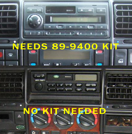
If you have the larger radio pictured above, you will need these radio removal tools:

If you have the smaller (lower) radio pictured above, you will need these radio removal tools:

REQUIRED PARTS FOR AFTERMARKET RADIO INSTALL

WIRING HARNESS

MOUNTING KIT FOR DOUBLE DIN AFTERMARKET RADIOS:

N/A

MOUNTING KIT FOR SINGLE DIN AFTERMARKET RADIOS:

Not needed for all vehicles see the pic above.

ANTENNA ADAPTER:

OEM AUX AUXILLIARY PORT RETENTION:

N/A

STEERING WHEEL CONTROL INTERFACE:

N/A

SPEAKER WIRING ADAPTERS FOR AFTERMARKET SPEAKER INSTALL:

N/A

SPEAKER MOUNTING ADAPTERS FOR AFTERMARKET SPEAKER INSTALL:

N/A

RECOMMENDED TOOLS FOR THE INSTALL – SAME ONES THE PROS USE!

– Klein Wire Cutters / Crimpers

– Dash Removal Plastic Pry Tools

– Gardner Bender Auto Wire Stripper

– Install Bay Butt Connectors

– 3M Electrical Tape

2007 Mazda CX-9 CX9 Audio Stereo Radio Bose Wiring Diagram Schematic Colors Install

Here is the stereo radio wiring information for your 2007 Mazda CX9 CX-9 body with the normal or Bose amplified systems. It will be useful when installing an aftermarket radio, sound stereo system, or other automotive accessories. Make sure to grab the appropriate tools to test all the wires in your CX-9. Please check it over and use it as a GUIDE to help you locate the appropriate wires. This schematic is provided free of charge and may not be 100% accurate. Failure to properly test all the wires may lead to vehicle or bodily damage. All information is provided as-is and accuracy is not guaranteed.

2007 Mazda CX-9 CX9 Audio Radio Bose Wiring Strereo Diagram Schematic Colors Install
2007 Mazda CX9 CX-9 Radio Audio Bose Wiring Strereo Diagram Schematic Colors Install

If you find any conflicting info please leave a comment with what you found in your Mazda CX9. If you don’t see the audio radio wiring diagram you need comment and we will try to add it ASAP. Thanks for looking!

2007 Mazda CX9 Stereo Audio Wiring Radio Diagram Schematic Colors – Aftermarket Install

Car Radio Constant 12v+ Wire: Red/Blue @ Radio Harness

Car Stereo Ground Wire: Black @ Main Radio Harness

Car Radio Ignition Switched Wire: Pink/Blue @ Main Radio Harness

Car Radio Illumination Wire: Red/Black @ Main Radio Harness

Reverse / Backup Wire: Red/Yellow (+) Driver Kick BCM or harness to rear

Car Radio Amp Turn On Wire: Purple/White @ 24-pin radio connector pin 6

Car Stereo Power Antenna: N/A @ Main Radio Harness

Non-Bose Speaker Wires At Radio:

Left Front Speaker (+) Positive: Dark Blue/Orange
Left Front Speaker (-) Negative: Lavender
Right Front Speaker (+) Positive: Gray/Blue
Right Front Speaker (-) Negative: Yellow/Green

Left Rear Speaker (+) Positive: Green
Left Rear Speaker (-) Negative: Green/Black
Right Rear Speaker (+) Positive: Yellow/Black
Right Rear Speaker (-) Negative: Yellow

SPEAKER WIRE COLORS AT THE AMP – RIGHT REAR QUARTER PANEL

Left Front Door Speaker Wire (+) Positive: Blue/Orange
Left Front Door Speaker Wire (-) Negative: Purple

Left Front Tweeter Speaker Wire (+) Positive: Red/White
Left Front Tweeter Speaker Wire (-) Negative: Red/Yellow

Right Front Door Speaker Wire (+) Positive: Gray/Blue
Right Front Door Speaker Wire (-) Negative: Yellow/Green

Right Front Tweeter Speaker Wire (+) Positive: Blue/White
Right Front Tweeter Speaker Wire (-) Negative: Blue/Red

Left Rear Door Speaker Wire (+) Positive: Green
Left Rear Door Speaker Wire (-) Negative: Green/Black

Right Rear Door Speaker Wire (+) Positive: Yellow/Black
Right Rear Door Speaker Wire (-) Negative: Yellow

Center Channel Speaker Wire Positive / Negative: N/A
Subwoofer Speaker Wire Positive / Negative: N/A

Retain OEM AUX In Center Console – 16-pin Connector at Back of Radio

Take a normal rca cable and cut one end off leaving yourself RCAs and a foot or two of slack. Strip the left and right ends twist the common shields together and then connect them to the following wires:

OEM AUX Left (+) Positive: White/Blue
OEM AUX Right (+) Positive: Red/Blue
OEM AUX Common Shield: Green/White (either green/white in this plug will work they are common)

Radio Size: Single or Double Din

Radio Removal Tools: – Dash Removal Plastic Pry Tools – Use these tools to help carefully unclip and remove both side panels from center radio trim panel. Carefully remove the shifter trim panel. Remove 1 screw from the trim panel with the power port then remove the panel. Remove 1 screw on the side of each vent holding the main radio trim panel on. Remove the main trim panel then remove 4 screws and pull the radio.

If you are installing a new aftermarket radio in your CX9 you need the wiring harness, the antenna adapter, steering wheel control module, and the mounting kit as well.

REQUIRED PARTS FOR AFTERMARKET RADIO INSTALL

MOUNTING KIT FOR SINGLE or DOUBLE DIN AFTERMARKET RADIOS:

WIRING HARNESS:

This harness can be used with the non-bose or bose systems. It will also retain your steering wheel controls no need for a separate adapter! Further yet no need to relocate the OEM radio for setting the clock functions or scrolling through the MPG – all can be done from the steering wheel!

ANTENNA ADAPTER:

N/A – Not needed

STEERING WHEEL CONTROLS ADAPTER:

Not needed if using the wiring harness above, otherwise this one below is great!

Metra Axxess ASWC-1 Universal Steering Wheel Control Interface

Adding A Backup Camera:

We’ve had great luck with this camera for a nice rear view. Mounted on the OEM lip above the license plate you see just a hair of the bumper in the image so you can really dial in your parking.

SPEAKER WIRING ADAPTERS:

N/A

RECOMMENDED TOOLS FOR THE INSTALL – SAME ONES THE PROS USE!

– 3M Electrical Tape

– Install Bay Butt Connectors

– Dash Removal Plastic Pry Tools

– Klein Wire Cutters / Crimpers

– Gardner Bender Auto Wire Stripper

2008 Mazda CX9 CX-9 Audio Radio Bose Wiring Stereo Diagram Schematic Colors Install

Here is the stereo radio wiring information for your 2008 Mazda CX-9 CX9 body with the normal or Bose amplified systems. It will be useful when installing an aftermarket radio, sound stereo system, or other automotive accessories. Make sure to grab the appropriate tools to test all the wires in your CX-9. Please check it over and use it as a GUIDE to help you locate the appropriate wires. This schematic is provided free of charge and may not be 100% accurate. Failure to properly test all the wires may lead to vehicle or bodily damage. All information is provided as-is and accuracy is not guaranteed.

2008 Mazda CX-9 CX9 Audio Wiring Diagram Schematic Colors Install

If you find any conflicting info please leave a comment with what you found in your Mazda CX9. If you don’t see the audio radio wiring diagram you need comment and we will try to add it ASAP. Thanks for looking!

2008 Mazda CX9 Audio Wiring Radio Diagram Schematic Colors – Aftermarket Stereo Install

Car Radio Constant 12v+ Wire: Red/Blue @ Radio Harness

Car Stereo Ground Wire: Black @ Main Radio Harness

Car Radio Ignition Switched Wire: Pink/Blue @ Main Radio Harness

Reverse / Backup Wire: Red/Yellow (+) Driver Kick BCM or harness to rear

Car Radio Illumination Wire: Red/Black @ Main Radio Harness

Car Radio Amp Turn On Wire: Purple/White @ 24-pin radio connector pin 6

Car Stereo Power Antenna: N/A @ Main Radio Harness

Non-Bose Speaker Wires At Radio:

Left Front Speaker (+) Positive: Dark Blue/Orange
Left Front Speaker (-) Negative: Lavender

Right Front Speaker (+) Positive: Gray/Blue
Right Front Speaker (-) Negative: Yellow/Green

Left Rear Speaker (+) Positive: Green
Left Rear Speaker (-) Negative: Green/Black

Right Rear Speaker (+) Positive: Yellow/Black
Right Rear Speaker (-) Negative: Yellow

SPEAKER WIRE COLORS AT THE AMP – RIGHT REAR QUARTER PANEL

Left Front Door Speaker Wire (+) Positive: Blue/Orange
Left Front Door Speaker Wire (-) Negative: Purple

Left Front Tweeter Speaker Wire (+) Positive: Red/White
Left Front Tweeter Speaker Wire (-) Negative: Red/Yellow

Right Front Door Speaker Wire (+) Positive: Gray/Blue
Right Front Door Speaker Wire (-) Negative: Yellow/Green

Right Front Tweeter Speaker Wire (+) Positive: Blue/White
Right Front Tweeter Speaker Wire (-) Negative: Blue/Red

Left Rear Door Speaker Wire (+) Positive: Green
Left Rear Door Speaker Wire (-) Negative: Green/Black

Right Rear Door Speaker Wire (+) Positive: Yellow/Black
Right Rear Door Speaker Wire (-) Negative: Yellow

Center Channel Speaker Wire Positive / Negative: N/A
Subwoofer Speaker Wire Positive / Negative: N/A

Retain OEM AUX In Center Console – 16-pin Connector at Back of Radio

Take a normal rca cable and cut one end off leaving yourself RCAs and a foot or two of slack. Strip the left and right ends twist the common shields together and then connect them to the following wires:

OEM AUX Left (+) Positive: White/Blue
OEM AUX Right (+) Positive: Red/Blue
OEM AUX Common Shield: Green/White (either green/white in this plug will work they are common)

Radio Size: Single or Double Din

Radio Removal Tools: – Dash Removal Plastic Pry Tools – Use these tools to help carefully unclip and remove both side panels from center radio trim panel. Carefully remove the shifter trim panel. Remove 1 screw from the trim panel with the power port then remove the panel. Remove 1 screw on the side of each vent holding the main radio trim panel on. Remove the main trim panel then remove 4 screws and pull the radio.

If you are installing a new aftermarket radio in your CX9 you need the wiring harness, the antenna adapter, steering wheel control module, and the mounting kit as well.

REQUIRED PARTS FOR AFTERMARKET RADIO INSTALL

MOUNTING KIT FOR SINGLE or DOUBLE DIN AFTERMARKET RADIOS:

WIRING HARNESS:

This harness can be used with the non-bose or bose systems. It will also retain your steering wheel controls no need for a separate adapter! Further yet no need to relocate the OEM radio for setting the clock functions or scrolling through the MPG – all can be done from the steering wheel!

ANTENNA ADAPTER:

N/A – Not needed

STEERING WHEEL CONTROLS ADAPTER:

Not needed if using the wiring harness above, otherwise this one below is great!

Metra Axxess ASWC-1 Universal Steering Wheel Control Interface

SPEAKER WIRING ADAPTERS:

N/A

Adding A Backup Camera:

We’ve had great luck with this camera for a nice rear view. Mounted on the OEM lip above the license plate you see just a hair of the bumper in the image so you can really dial in your parking.

RECOMMENDED TOOLS FOR THE INSTALL – SAME ONES THE PROS USE!

– 3M Electrical Tape

– Install Bay Butt Connectors

– Dash Removal Plastic Pry Tools

– Gardner Bender Auto Wire Stripper

– Klein Wire Cutters / Crimpers

2009 Mazda CX9 CX-9 Audio Radio Bose Wiring Diagram Schematic Colors Install

Here is the stereo radio wiring information for your 2009 Mazda CX-9 CX9 body with the standard or Bose amplified systems. It will be useful when installing an aftermarket radio, sound stereo system, or other automotive accessories. Make sure to grab the appropriate tools to test all the wires in your CX-9. Please check it over and use it as a GUIDE to help you locate the appropriate wires. This schematic is provided free of charge and may not be 100% accurate. Failure to properly test all the wires may lead to vehicle or bodily damage. All information is provided as-is and accuracy is not guaranteed.

2009 Mazda CX-9 CX9 Radio Audio Bose Wiring Schematic Diagram Colors Install

If you find any conflicting info please leave a comment with what you found in your Mazda CX-9. If you don’t see the audio radio wiring diagram you need comment and we will try to add it ASAP. Thanks for looking!

2009 Mazda CX9 CX-9 Audio Wiring Radio Diagram Schematic Colors – Aftermarket Stereo Installation Help

Car Radio Constant 12v+ Wire: Red/Blue @ Radio Harness

Car Stereo Ground Wire: Black @ Main Radio Harness

Car Radio Ignition Switched Wire: Pink/Blue @ Radio Harness

Reverse / Backup Wire: Red/Yellow (+) Driver Kick BCM or harness to rear

Car Radio Illumination Wire: Red/Black @ Main Radio Harness

Car Radio Amp Turn On Wire: Purple/White @ 24-pin radio connector pin 6

Car Stereo Power Antenna: N/A @ Main Radio Harness

Non-Bose Speaker Wires At Radio:

Left Front Speaker (+) Positive: Dark Blue/Orange
Left Front Speaker (-) Negative: Purple

Right Front Speaker (+) Positive: Gray/Blue
Right Front Speaker (-) Negative: Yellow/Green

Left Rear Speaker (+) Positive: Green
Left Rear Speaker (-) Negative: Green/Black

Right Rear Speaker (+) Positive: Yellow/Black
Right Rear Speaker (-) Negative: Yellow

SPEAKER WIRE COLORS AT AMP IN THE RIGHT REAR QUARTER PANEL

Left Front Door Speaker Wire (+) Positive: Blue/Orange
Left Front Door Speaker Wire (-) Negative: Purple

Left Front Tweeter Speaker Wire (+) Positive: Red/White
Left Front Tweeter Speaker Wire (-) Negative: Red/Yellow

Right Front Door Speaker Wire (+) Positive: Gray/Blue
Right Front Door Speaker Wire (-) Negative: Yellow/Green

Right Front Tweeter Speaker Wire (+) Positive: Blue/White
Right Front Tweeter Speaker Wire (-) Negative: Blue/Red

Left Rear Door Speaker Wire (+) Positive: Green
Left Rear Door Speaker Wire (-) Negative: Green/Black

Right Rear Door Speaker Wire (+) Positive: Yellow/Black
Right Rear Door Speaker Wire (-) Negative: Yellow

Subwoofer Speaker Wire Positive / Negative: N/A

Center Channel Speaker Wire Positive / Negative: N/A

Retain OEM AUX In Center Console – 16-pin Connector at Back of Radio

Take a normal rca cable and cut one end off leaving yourself RCAs and a foot or two of slack. Strip the left and right ends twist the common shields together and then connect them to the following wires:

OEM AUX Left (+) Positive: White/Blue
OEM AUX Right (+) Positive: Red/Blue
OEM AUX Common Shield: Green/White (either green/white in this plug will work they are common)

Radio Size: Single or Double Din

Radio Removal Tools: – Dash Removal Plastic Pry Tools – Use these tools to help carefully unclip and remove both side panels from center radio trim panel. Carefully remove the shifter trim panel. Remove 1 screw from the trim panel with the power port then remove the panel. Remove 1 screw on the side of each vent holding the main radio trim panel on. Remove the main trim panel then remove 4 screws and pull the radio.

If you are installing a new aftermarket radio in your CX9 you need the wiring harness, the antenna adapter, steering wheel control module, and the mounting kit as well.

REQUIRED PARTS FOR AFTERMARKET RADIO INSTALL

MOUNTING KIT FOR SINGLE or DOUBLE DIN AFTERMARKET RADIOS:

WIRING HARNESS:

This harness can be used with the non-bose or bose systems. It will also retain your steering wheel controls no need for a separate adapter! Further yet no need to relocate the OEM radio for setting the clock functions or scrolling through the MPG – all can be done from the steering wheel!

ANTENNA ADAPTER:

N/A – Not needed

SPEAKER WIRING ADAPTERS:

N/A

STEERING WHEEL CONTROLS ADAPTER:

Not needed if using the wiring harness above, otherwise this one below is great!

Metra Axxess ASWC-1 Universal Steering Wheel Control Interface

Adding A Backup Camera:

We’ve had great luck with this camera for a nice rear view. Mounted on the OEM lip above the license plate you see just a hair of the bumper in the image so you can really dial in your parking.

RECOMMENDED TOOLS FOR THE INSTALL – SAME ONES THE PROS USE!

– 3M Electrical Tape

– Dash Removal Plastic Pry Tools

– Klein Wire Cutters / Crimpers

– Install Bay Butt Connectors

– Gardner Bender Auto Wire Stripper

2010 Mazda CX-9 CX9 Radio Audio Bose Wiring Schematic Diagram Colors Install

Here is the stereo radio wiring information for your 2010 Mazda CX-9 CX9 body with the standard or Bose amplified systems. It will be useful when installing an aftermarket radio, sound stereo system, or other automotive accessories. Make sure to grab the appropriate tools to test all the wires in your CX-9. Please check it over and use it as a GUIDE to help you locate the appropriate wires. This schematic is provided free of charge and may not be 100% accurate. Failure to properly test all the wires may lead to vehicle or bodily damage. All information is provided as-is and accuracy is not guaranteed.

2010 Mazda CX-9 CX9 Radio Audio Bose Wiring Diagram Schematic Colors Install
2010 Mazda CX-9 CX9 Radio Stereo Audio Bose Wiring Diagram Schematic Colors Install

If you find any conflicting info please leave a comment with what you found in your Mazda CX-9. If you don’t see the audio radio wiring diagram you need comment and we will try to add it ASAP. Thanks for looking!

2010 Mazda CX-9 Audio Wiring Radio Diagram Schematic Colors – Aftermarket Stereo Installation Help

Car Radio Constant 12v+ Wire: Red/Blue @ Radio Harness
Car Stereo Ground Wire: Black @ Radio Harness
Car Radio Ignition Switched Wire: Pink/Blue @ Radio Harness

Reverse / Backup Wire: Red/Yellow (+) Driver Kick BCM or harness to rear

Car Radio Illumination Wire: Red/Black @ Main Radio Harness

Car Radio Amp Turn On Wire: Purple/White @ 24-pin radio connector pin 6

Car Stereo Power Antenna: N/A @ Main Radio Harness

Non-Bose Speaker Wires At Radio:

Left Front Speaker (+) Positive: Dark Blue/Orange
Left Front Speaker (-) Negative: Purple

Right Front Speaker (+) Positive: Gray/Blue
Right Front Speaker (-) Negative: Yellow/Green

Left Rear Speaker (+) Positive: Green
Left Rear Speaker (-) Negative: Green/Black

Right Rear Speaker (+) Positive: Yellow/Black
Right Rear Speaker (-) Negative: Yellow

SPEAKER WIRE COLORS AT AMP IN THE RIGHT REAR QUARTER PANEL

Left Front Door Speaker Wire (+) Positive: Blue/Orange
Left Front Door Speaker Wire (-) Negative: Purple

Left Front Tweeter Speaker Wire (+) Positive: Red/White
Left Front Tweeter Speaker Wire (-) Negative: Red/Yellow

Right Front Door Speaker Wire (+) Positive: Gray/Blue
Right Front Door Speaker Wire (-) Negative: Yellow/Green

Right Front Tweeter Speaker Wire (+) Positive: Blue/White
Right Front Tweeter Speaker Wire (-) Negative: Blue/Red

Left Rear Door Speaker Wire (+) Positive: Green
Left Rear Door Speaker Wire (-) Negative: Green/Black

Right Rear Door Speaker Wire (+) Positive: Yellow/Black
Right Rear Door Speaker Wire (-) Negative: Yellow

Subwoofer Speaker Wire Positive / Negative: N/A

Center Channel Speaker Wire Positive / Negative: N/A

Retain OEM AUX In Center Console – 16-pin Connector at Back of Radio

Take a normal rca cable and cut one end off leaving yourself RCAs and a foot or two of slack. Strip the left and right ends twist the common shields together and then connect them to the following wires:

OEM AUX Left (+) Positive: White/Blue
OEM AUX Right (+) Positive: Red/Blue
OEM AUX Common Shield: Green/White (either green/white in this plug will work they are common)

Radio Size: Single or Double Din

Radio Removal Tools: – Dash Removal Plastic Pry Tools – Use these tools to help carefully unclip and remove both side panels from center radio trim panel. Carefully remove the shifter trim panel. Remove 1 screw from the trim panel with the power port then remove the panel. Remove 1 screw on the side of each vent holding the main radio trim panel on. Remove the main trim panel then remove 4 screws and pull the radio.

If you are installing a new aftermarket radio in your CX9 you need the wiring harness, the antenna adapter, steering wheel control module, and the mounting kit as well.

REQUIRED PARTS FOR AFTERMARKET RADIO INSTALL

MOUNTING KIT FOR SINGLE or DOUBLE DIN AFTERMARKET RADIOS:

WIRING HARNESS:

This harness can be used with the non-bose or bose systems. It will also retain your steering wheel controls no need for a separate adapter! Further yet no need to relocate the OEM radio for setting the clock functions or scrolling through the MPG – all can be done from the steering wheel!

ANTENNA ADAPTER:

N/A – Not needed

STEERING WHEEL CONTROLS ADAPTER:

Not needed if using the wiring harness above, otherwise this one below is great!

Metra Axxess ASWC-1 Universal Steering Wheel Control Interface

SPEAKER WIRING ADAPTERS:

N/A

Adding A Backup Camera:

We’ve had great luck with this camera for a nice rear view. Mounted on the OEM lip above the license plate you see just a hair of the bumper in the image so you can really dial in your parking.

RECOMMENDED TOOLS FOR THE INSTALL – SAME ONES THE PROS USE!

– 3M Electrical Tape

– Dash Removal Plastic Pry Tools

– Install Bay Butt Connectors

– Gardner Bender Auto Wire Stripper

– Klein Wire Cutters / Crimpers

2011 Mazda CX-9 CX9 Radio Audio Bose Wiring Schematic Diagram Colors Install

Here is the stereo radio wiring information for your 2011 Mazda CX9 CX-9 body with the standard or Bose amplified systems. It will be useful when installing an aftermarket radio, sound stereo system, or other automotive accessories. Make sure to grab the appropriate tools to test all the wires in your CX-9. Please check it over and use it as a GUIDE to help you locate the appropriate wires. This schematic is provided free of charge and may not be 100% accurate. Failure to properly test all the wires may lead to vehicle or bodily damage. All information is provided as-is and accuracy is not guaranteed.

2011 Mazda CX-9 CX9 Radio Audio Bose Wiring Diagram Schematic Colors Install

If you find any conflicting info please leave a comment with what you found in your Mazda CX-9. If you don’t see the audio radio wiring diagram you need comment and we will try to add it ASAP. Thanks for looking!

2011 Mazda CX-9 Audio Wiring Radio Diagram Schematic Colors – Aftermarket Stereo Installation Help

Car Radio Constant 12v+ Wire: Red/Blue @ Main Radio Harness
Car Stereo Ground Wire: Black @ Main Radio Harness
Car Radio Ignition Switched Wire: Pink/Blue @ Main Radio Harness

Reverse / Backup Wire: Red/Yellow (+) Driver Kick BCM or harness to rear

Car Radio Illumination Wire: Red/Black @ Main Radio Harness

Car Stereo Power Antenna: N/A @ Main Radio Harness
Car Radio Amp Turn On Wire: Purple/White @ 24-pin radio connector pin 6

Non-Bose Speaker Wires At Radio:

Left Front Speaker (+) Positive: Dark Blue/Orange
Left Front Speaker (-) Negative: Lavender
Right Front Speaker (+) Positive: Gray/Blue
Right Front Speaker (-) Negative: Yellow/Green

Left Rear Speaker (+) Positive: Green
Left Rear Speaker (-) Negative: Green/Black
Right Rear Speaker (+) Positive: Yellow/Black
Right Rear Speaker (-) Negative: Yellow

SPEAKER WIRE COLORS AT AMP – RIGHT REAR QUARTER PANEL

Left Front Door Speaker Wire (+) Positive: Blue/Orange
Left Front Door Speaker Wire (-) Negative: Purple

Left Front Tweeter Speaker Wire (+) Positive: Red/White
Left Front Tweeter Speaker Wire (-) Negative: Red/Yellow

Right Front Door Speaker Wire (+) Positive: Gray/Blue
Right Front Door Speaker Wire (-) Negative: Yellow/Green

Right Front Tweeter Speaker Wire (+) Positive: Blue/White
Right Front Tweeter Speaker Wire (-) Negative: Blue/Red

Left Rear Door Speaker Wire (+) Positive: Green
Left Rear Door Speaker Wire (-) Negative: Green/Black

Right Rear Door Speaker Wire (+) Positive: Yellow/Black
Right Rear Door Speaker Wire (-) Negative: Yellow

Subwoofer Speaker Wire Positive / Negative: N/A

Center Channel Speaker Wire Positive / Negative: N/A

Retain OEM AUX In Center Console – 16-pin Connector at Back of Radio

Take a normal rca cable and cut one end off leaving yourself RCAs and a foot or two of slack. Strip the left and right ends twist the common shields together and then connect them to the following wires:

OEM AUX Left (+) Positive: White/Blue
OEM AUX Right (+) Positive: Red/Blue
OEM AUX Common Shield: Green/White (either green/white in this plug will work they are common)

Radio Size: Single or Double Din

Radio Removal Tools: – Dash Removal Plastic Pry Tools – Use these tools to help carefully unclip and remove both side panels from center radio trim panel. Carefully remove the shifter trim panel. Remove 1 screw from the trim panel with the power port then remove the panel. Remove 1 screw on the side of each vent holding the main radio trim panel on. Remove the main trim panel then remove 4 screws and pull the radio.

If you are installing a new aftermarket radio in your CX9 you need the wiring harness, the antenna adapter, steering wheel control module, and the mounting kit as well.

REQUIRED PARTS FOR AFTERMARKET RADIO INSTALL

WIRING HARNESS:

This harness can be used with the non-bose or bose systems. It will also retain your steering wheel controls no need for a separate adapter! Further yet no need to relocate the OEM radio for setting the clock functions or scrolling through the MPG – all can be done from the steering wheel!

MOUNTING KIT FOR SINGLE or DOUBLE DIN AFTERMARKET RADIOS:

ANTENNA ADAPTER:

N/A – Not needed

STEERING WHEEL CONTROLS ADAPTER:

Not needed if using the wiring harness above, otherwise this one below is great!

Metra Axxess ASWC-1 Universal Steering Wheel Control Interface

SPEAKER WIRING ADAPTERS:

N/A

Adding A Backup Camera:

We’ve had great luck with this camera for a nice rear view. Mounted on the OEM lip above the license plate you see just a hair of the bumper in the image so you can really dial in your parking.

RECOMMENDED TOOLS FOR THE INSTALL – SAME ONES THE PROS USE!

– 3M Electrical Tape

– Install Bay Butt Connectors

– Dash Removal Plastic Pry Tools

– Gardner Bender Auto Wire Stripper

– Klein Wire Cutters / Crimpers

2014 Mazda CX9 CX-9 Radio Stereo Audio Bose Wiring Diagram Schematic Colors Install

Here is the stereo radio wiring information for your 2014 Mazda CX-9 CX9 body with the standard or Bose amplified systems. It will be useful when installing an aftermarket radio, sound stereo system, or other automotive accessories. Make sure to grab the appropriate tools to test all the wires in your CX-9. Please check it over and use it as a GUIDE to help you locate the appropriate wires. This schematic is provided free of charge and may not be 100% accurate. Failure to properly test all the wires may lead to vehicle or bodily damage. All information is provided as-is and accuracy is not guaranteed.

2014 Mazda CX-9 CX9 Radio Audio Bose Wiring Diagram Schematic Colors Install

If you find any conflicting info please leave a comment with what you found in your Mazda CX9. If you don’t see the audio radio wiring diagram you need comment and we will try to add it ASAP. Thanks for looking!

2014 Mazda CX9 Audio Wiring Radio Diagram Schematic Colors – Aftermarket Stereo Installation Help

Car Radio Constant 12v+ Wire: Red/Blue @ Main Radio Harness
Car Stereo Ground Wire: Black @ Main Radio Harness
Car Radio Ignition Switched Wire: Pink/Blue @ Main Radio Harness

Car Radio Illumination Wire: Red/Black @ Main Radio Harness

Car Radio Amp Turn On Wire: Purple/White @ 24-pin radio connector pin 6
Car Stereo Power Antenna: N/A @ Main Radio Harness

Reverse / Backup Wire: Red/Yellow (+) Driver Kick BCM or harness to rear

Non-Bose Speaker Wires At Radio:

Left Front Speaker (+) Positive: Dark Blue/Orange
Left Front Speaker (-) Negative: Lavender

Right Front Speaker (+) Positive: Gray/Blue
Right Front Speaker (-) Negative: Yellow/Green

Left Rear Speaker (+) Positive: Green
Left Rear Speaker (-) Negative: Green/Black

Right Rear Speaker (+) Positive: Yellow/Black
Right Rear Speaker (-) Negative: Yellow

STEREO SPEAKER WIRE COLORS AT THE AMP – RIGHT REAR QUARTER PANEL

Left Front Door Speaker Wire (+) Positive: Blue/Orange
Left Front Door Speaker Wire (-) Negative: Lavender

Left Front Tweeter Speaker Wire (+) Positive: Red/White
Left Front Tweeter Speaker Wire (-) Negative: Red/Yellow

Right Front Door Speaker Wire (+) Positive: Gray/Blue
Right Front Door Speaker Wire (-) Negative: Yellow/Green

Right Front Tweeter Speaker Wire (+) Positive: Blue/White
Right Front Tweeter Speaker Wire (-) Negative: Blue/Red

Left Rear Door Speaker Wire (+) Positive: Green
Left Rear Door Speaker Wire (-) Negative: Green/Black

Right Rear Door Speaker Wire (+) Positive: Yellow/Black
Right Rear Door Speaker Wire (-) Negative: Yellow

Subwoofer Speaker Wire Positive / Negative: N/A

Center Channel Speaker Wire Positive / Negative: N/A

Retain OEM AUX In Center Console – 16-pin Connector at Back of Radio

Take a normal rca cable and cut one end off leaving yourself RCAs and a foot or two of slack. Strip the left and right ends twist the common shields together and then connect them to the following wires:

OEM AUX Left (+) Positive: White/Blue
OEM AUX Right (+) Positive: Red/Blue
OEM AUX Common Shield: Green/White (either green/white in this plug will work they are common)

Radio Size: Single or Double Din

Radio Removal Tools: – Dash Removal Plastic Pry Tools – Use these tools to help carefully unclip and remove both side panels from center radio trim panel. Carefully remove the shifter trim panel. Remove 1 screw from the trim panel with the power port then remove the panel. Remove 1 screw on the side of each vent holding the main radio trim panel on. Remove the main trim panel then remove 4 screws and pull the radio.

If you are installing a new aftermarket radio in your CX-9 you need the wiring harness, the antenna adapter, steering wheel control module, and the mounting kit as well.

REQUIRED PARTS FOR AFTERMARKET RADIO INSTALL

MOUNTING KIT FOR SINGLE or DOUBLE DIN AFTERMARKET RADIOS:

WIRING HARNESS:

This harness can be used with the non-bose or bose systems. It will also retain your steering wheel controls no need for a separate adapter! Further yet no need to relocate the OEM radio for setting the clock functions or scrolling through the MPG – all can be done from the steering wheel!

STEERING WHEEL CONTROLS ADAPTER:

Not needed if using the wiring harness above, otherwise this one below is great!

Metra Axxess ASWC-1 Universal Steering Wheel Control Interface

ANTENNA ADAPTER:

N/A – Not needed

SPEAKER WIRING ADAPTERS:

N/A

Adding A Backup Camera:

We’ve had great luck with this camera for a nice rear view. Mounted on the OEM lip above the license plate you see just a hair of the bumper in the image so you can really dial in your parking.

RECOMMENDED TOOLS FOR THE INSTALL – SAME ONES THE PROS USE!

– 3M Electrical Tape

– Install Bay Butt Connectors

– Gardner Bender Auto Wire Stripper

– Klein Wire Cutters / Crimpers

– Dash Removal Plastic Pry Tools

2013 Mazda CX-9 CX9 Radio Audio Bose Wiring Diagram Schematic Colors Install

Here is the stereo radio wiring information for your 2013 Mazda CX9 CX-9 body with the standard or Bose amplified systems. It will be useful when installing an aftermarket radio, sound stereo system, or other automotive accessories. Make sure to grab the appropriate tools to test all the wires in your CX-9. Please check it over and use it as a GUIDE to help you locate the appropriate wires. This schematic is provided free of charge and may not be 100% accurate. Failure to properly test all the wires may lead to vehicle or bodily damage. All information is provided as-is and accuracy is not guaranteed.

2013 Mazda CX-9 CX9 Radio Audio Bose Wiring Diagram Schematic Colors Install

If you find any conflicting info please leave a comment with what you found in your Mazda CX9. If you don’t see the audio radio wiring diagram you need comment and we will try to add it ASAP. Thanks for looking!

2013 Mazda CX9 Audio Wiring Radio Diagram Schematic Colors – Aftermarket Stereo Installation Help

Car Radio Constant 12v+ Wire: Red/Blue @ Main Radio Harness
Car Stereo Ground Wire: Black @ Main Radio Harness
Car Radio Ignition Switched Wire: Pink/Blue @ Main Radio Harness

Car Radio Illumination Wire: Red/Black @ Main Radio Harness

Car Stereo Power Antenna: N/A @ Main Radio Harness
Car Radio Amp Turn On Wire: Purple/White @ 24-pin radio connector pin 6

Reverse / Backup Wire: Red/Yellow (+) Driver Kick BCM or harness to rear

Non-Bose Speaker Wires At Radio:

Left Front Speaker (+) Positive: Dark Blue/Orange
Left Front Speaker (-) Negative: Lavender
Right Front Speaker (+) Positive: Gray/Blue
Right Front Speaker (-) Negative: Yellow/Green

Left Rear Speaker (+) Positive: Green
Left Rear Speaker (-) Negative: Green/Black
Right Rear Speaker (+) Positive: Yellow/Black
Right Rear Speaker (-) Negative: Yellow

SPEAKER WIRE COLORS AT AMP – RIGHT REAR QUARTER PANEL

Left Front Door Speaker Wire (+) Positive: Blue/Orange
Left Front Door Speaker Wire (-) Negative: Purple
Left Front Tweeter Speaker Wire (+) Positive: Red/White
Left Front Tweeter Speaker Wire (-) Negative: Red/Yellow

Right Front Door Speaker Wire (+) Positive: Gray/Blue
Right Front Door Speaker Wire (-) Negative: Yellow/Green
Right Front Tweeter Speaker Wire (+) Positive: Blue/White
Right Front Tweeter Speaker Wire (-) Negative: Blue/Red

Left Rear Door Speaker Wire (+) Positive: Green
Left Rear Door Speaker Wire (-) Negative: Green/Black

Right Rear Door Speaker Wire (+) Positive: Yellow/Black
Right Rear Door Speaker Wire (-) Negative: Yellow

Subwoofer Speaker Wire Positive / Negative: N/A

Center Channel Speaker Wire Positive / Negative: N/A

Retain OEM AUX In Center Console – 16-pin Connector at Back of Radio

Take a normal rca cable and cut one end off leaving yourself RCAs and a foot or two of slack. Strip the left and right ends twist the common shields together and then connect them to the following wires:

OEM AUX Left (+) Positive: White/Blue
OEM AUX Right (+) Positive: Red/Blue
OEM AUX Common Shield: Green/White (either green/white in this plug will work they are common)

Radio Size: Single or Double Din

Radio Removal Tools: – Dash Removal Plastic Pry Tools – Use these tools to help carefully unclip and remove both side panels from center radio trim panel. Carefully remove the shifter trim panel. Remove 1 screw from the trim panel with the power port then remove the panel. Remove 1 screw on the side of each vent holding the main radio trim panel on. Remove the main trim panel then remove 4 screws and pull the radio.

If you are installing a new aftermarket radio in your CX-9 you need the wiring harness, the antenna adapter, steering wheel control module, and the mounting kit as well.

REQUIRED PARTS FOR AFTERMARKET RADIO INSTALL

MOUNTING KIT FOR SINGLE or DOUBLE DIN AFTERMARKET RADIOS:

WIRING HARNESS:

This harness can be used with the non-bose or bose systems. It will also retain your steering wheel controls no need for a separate adapter! Further yet no need to relocate the OEM radio for setting the clock functions or scrolling through the MPG – all can be done from the steering wheel!

ANTENNA ADAPTER:

N/A – Not needed

STEERING WHEEL CONTROLS ADAPTER:

Not needed if using the wiring harness above, otherwise this one below is great!

Metra Axxess ASWC-1 Universal Steering Wheel Control Interface

SPEAKER WIRING ADAPTERS:

N/A

Adding A Backup Camera:

We’ve had great luck with this camera for a nice rear view. Mounted on the OEM lip above the license plate you see just a hair of the bumper in the image so you can really dial in your parking.

RECOMMENDED TOOLS FOR THE INSTALL – SAME ONES THE PROS USE!

– 3M Electrical Tape

– Install Bay Butt Connectors

– Gardner Bender Auto Wire Stripper

– Klein Wire Cutters / Crimpers

– Dash Removal Plastic Pry Tools

2012 Mazda CX-9 CX9 Radio Audio Bose Wiring Diagram Schematic Colors Install

Here is the stereo radio wiring information for your 2012 Mazda CX9 CX-9 body with the standard or Bose amplified systems. It will be useful when installing an aftermarket radio, sound stereo system, or other automotive accessories. Make sure to grab the appropriate tools to test all the wires in your CX-9. Please check it over and use it as a GUIDE to help you locate the appropriate wires. This schematic is provided free of charge and may not be 100% accurate. Failure to properly test all the wires may lead to vehicle or bodily damage. All information is provided as-is and accuracy is not guaranteed.

2012 Mazda CX9 Audio Wiring Diagram Schematic Colors Install

If you find any conflicting info please leave a comment with what you found in your Mazda CX9. If you don’t see the audio radio wiring diagram you need comment and we will try to add it ASAP. Thanks for looking!

2012 Mazda CX9 Audio Wiring Radio Diagram Schematic Colors – Aftermarket Stereo Installation Help

Car Radio Constant 12v+ Wire: Red/Blue @ Main Radio Harness
Car Stereo Ground Wire: Black @ Main Radio Harness
Car Radio Ignition Switched Wire: Pink/Blue @ Main Radio Harness
Car Radio Illumination Wire: Red/Black @ Main Radio Harness
Car Stereo Power Antenna: N/A @ Main Radio Harness
Car Radio Amp Turn On Wire: Purple/White @ 24-pin radio connector pin 6

Reverse / Backup Wire: Red/Yellow (+) Driver Kick BCM or harness to rear

Non-Bose Speaker Wires At Radio:

Left Front Speaker (+) Positive: Dark Blue/Orange
Left Front Speaker (-) Negative: Lavender
Right Front Speaker (+) Positive: Gray/Blue
Right Front Speaker (-) Negative: Yellow/Green

Left Rear Speaker (+) Positive: Green
Left Rear Speaker (-) Negative: Green/Black
Right Rear Speaker (+) Positive: Yellow/Black
Right Rear Speaker (-) Negative: Yellow

SPEAKER WIRE COLORS AT THE AMP IN RIGHT REAR QUARTER PANEL

Left Front Door Speaker Wire (+) Positive: Blue/Orange
Left Front Door Speaker Wire (-) Negative: Purple

Left Front Tweeter Speaker Wire (+) Positive: Red/White
Left Front Tweeter Speaker Wire (-) Negative: Red/Yellow

Right Front Door Speaker Wire (+) Positive: Gray/Blue
Right Front Door Speaker Wire (-) Negative: Yellow/Green

Right Front Tweeter Speaker Wire (+) Positive: Blue/White
Right Front Tweeter Speaker Wire (-) Negative: Blue/Red

Left Rear Door Speaker Wire (+) Positive: Green
Left Rear Door Speaker Wire (-) Negative: Green/Black

Right Rear Door Speaker Wire (+) Positive: Yellow/Black
Right Rear Door Speaker Wire (-) Negative: Yellow

Center Channel Speaker Wire Positive / Negative: N/A

Subwoofer Speaker Wire Positive / Negative: N/A

Retain OEM AUX In Center Console – 16-pin Connector at Back of Radio

Take a normal rca cable and cut one end off leaving yourself RCAs and a foot or two of slack. Strip the left and right ends twist the common shields together and then connect them to the following wires:

OEM AUX Left (+) Positive: White/Blue
OEM AUX Right (+) Positive: Red/Blue
OEM AUX Common Shield: Green/White (either green/white in this plug will work they are common)

Radio Size: Single or Double Din

Radio Removal Tools: – Dash Removal Plastic Pry Tools – Use these tools to help carefully unclip and remove both side panels from center radio trim panel. Carefully remove the shifter trim panel. Remove 1 screw from the trim panel with the power port then remove the panel. Remove 1 screw on the side of each vent holding the main radio trim panel on. Remove the main trim panel then remove 4 screws and pull the radio.

Keep in mind if you are installing a new radio in your CX-9 you need the wiring harness, the antenna adapter, steering wheel control module, and the mounting kit as well.

REQUIRED PARTS FOR AFTERMARKET RADIO INSTALL

WIRING HARNESS:

This harness can be used with the non-bose or bose systems. It will also retain your steering wheel controls no need for a separate adapter! Further yet no need to relocate the OEM radio for setting the clock functions or scrolling through the MPG – all can be done from the steering wheel!

MOUNTING KIT FOR SINGLE or DOUBLE DIN AFTERMARKET RADIOS:

ANTENNA ADAPTER:

N/A – Not needed

STEERING WHEEL CONTROLS ADAPTER:

Not needed if using the wiring harness above, otherwise this one below is great!

Metra Axxess ASWC-1 Universal Steering Wheel Control Interface

SPEAKER WIRING ADAPTERS:

N/A

Adding A Backup Camera:

We’ve had great luck with this camera for a nice rear view. Mounted on the OEM lip above the license plate you see just a hair of the bumper in the image so you can really dial in your parking.

RECOMMENDED TOOLS FOR THE INSTALL – SAME ONES THE PROS USE!

– 3M Electrical Tape

– Install Bay Butt Connectors

– Gardner Bender Auto Wire Stripper

– Klein Wire Cutters / Crimpers

– Dash Removal Plastic Pry Tools

2010 Subaru Legacy Radio Audio Harmon Kardon Wiring Diagram Schematic Colors Install

Here is the stereo radio wiring information for your 2010 Subaru Legacy body with the standard or Harmon Kardon H/K amplified systems. It will be useful when installing an aftermarket radio, sound stereo system, or other automotive accessories. Make sure to grab the appropriate tools to test all the wires in your Legacy. Please check it over and use it as a GUIDE to help you locate the appropriate wires. This schematic is provided free of charge and may not be 100% accurate. Failure to properly test all the wires may lead to vehicle or bodily damage. All information is provided as-is and accuracy is not guaranteed.

2010 Subaru Legacy Radio Audio Wiring Diagram Schematic Colors Install
2010 Subaru Legacy Harmon Kardon Radio Audio Wiring Diagram Schematic Colors Install

If you find any conflicting info please leave a comment with what you found in your Subaru Legacy. If you don’t see the audio radio wiring diagram you need comment and we will try to add it ASAP. Thanks for looking!

2010 Subaru Legacy Harmon Kardon Audio Wiring Radio Diagram Schematic Colors – Aftermarket Stereo Installation Help

Car Radio Constant 12v+ Wire: Green/White @ Main Radio Harness
Car Stereo Ground Wire: Black @ Main Radio Harness
Car Radio Ignition Switched Wire: Yellow/Red @ Main Radio Harness
Car Radio Illumination Wire: Purple @ Main Radio Harness
Car Stereo Power Antenna: Yellow/Black @ Main Radio Harness
Car Radio Amp Turn On Wire: Pink @ 24-pin radio connector pin 23

Reverse / Backup Wire: Brown/Yellow (+) Driver Kick White 13-pin plug

Left Front Speaker Amp Feed Wire (+) Positive: Black
Left Front Speaker Amp Feed Wire (-) Negative: Green
Right Front Speaker Amp Feed Wire (+) Positive: Red
Right Front Speaker Amp Feed Wire (-) Negative: White

Left Rear Speaker Amp Feed Wire (+) Positive: White/Blue
Left Rear Speaker Amp Feed Wire (-) Negative: Orange/Green
Right Rear Speaker Amp Feed Wire (+) Positive: Blue/Yellow
Right Rear Speaker Amp Feed Wire (-) Negative: Blue

SPEAKER WIRE COLORS AT THE AMP UNDER PASSENGER SEAT

Left Front Door Speaker Wire (+) Positive: Brown
Left Front Door Speaker Wire (-) Negative: Green

Left Front Tweeter Speaker Wire (+) Positive: Green/Yellow
Left Front Tweeter Speaker Wire (-) Negative: Purple

Right Front Door Speaker Wire (+) Positive: Black/Red
Right Front Door Speaker Wire (-) Negative: White/Red

Right Front Tweeter Speaker Wire (+) Positive: Yellow
Right Front Tweeter Speaker Wire (-) Negative: White/Green

Left Rear Door Speaker Wire (+) Positive: Black/Blue
Left Rear Door Speaker Wire (-) Negative: White/Blue

Right Rear Door Speaker Wire (+) Positive: Black
Right Rear Door Speaker Wire (-) Negative: Yellow

Center Channel Speaker Wire Positive / Negative: N/A

Subwoofer Speaker Wire Positive / Negative: No special wiring is needed to retain.

Retain OEM USB In Center Console

This cable will plugin behind the radio and keep your OEM USB functional with a new aftermarket radio:

Retain OEM AUX In Center Console

Take a normal rca cable and cut one end off leaving yourself RCAs and a foot or two of slack. Strip the left and right ends twist the common shields together and then connect them to the following wires:

OEM AUX Left (+) Positive: White – On models with OEM Bluetooth @ White 24 Plug Pin 7
OEM AUX Right (+) Positive: Red – On models with OEM Bluetooth @ White 24 Plug Pin 8
OEM AUX Common Shield: Gray – On models with OEM Bluetooth @ White 24 Plug Pin 19

Radio Size: Single or Double Din

Radio Removal Tools: – Dash Removal Plastic Pry Tools – Use the pry tools to remove the bezel surrounding the radio. After that use a Phillips screwdriver the radio is held in with 4 screws.

Keep in mind if you are installing a new radio in your Legacy you need the wiring harness, the antenna adapter, steering wheel control module, and the mounting kit as well.

REQUIRED PARTS FOR AFTERMARKET RADIO INSTALL

BASE SYSTEM WIRING HARNESS:

(Description may say for Nissan but it is the right one!)

Not as common but some models/options may require the following harness instead:

HARMON KARDON SYSTEM WIRING HARNESS:

(Description may say for Nissan but it is the right one!)
(Make sure to hook up the Pink amp turn on wire listed above or you will get no sound!)

MOUNTING KIT FOR DOUBLE DIN AFTERMARKET RADIOS:

(CARS WITHOUT OEM NAV ONLY)

BLACK:

SILVER:

MOUNTING KIT FOR SINGLE DIN AFTERMARKET RADIOS:

BLACK:

ANTENNA ADAPTER:

STEERING WHEEL CONTROLS ADAPTER:

Metra Axxess ASWC-1 Universal Steering Wheel Control Interface

SPEAKER WIRING ADAPTERS:

N/A

RECOMMENDED TOOLS FOR THE INSTALL – SAME ONES THE PROS USE!

– 3M Electrical Tape

– Install Bay Butt Connectors

– Gardner Bender Auto Wire Stripper

– Klein Wire Cutters / Crimpers

– Dash Removal Plastic Pry Tools