Here is the info on how to bypass the parking brake lockout on the Pioneer AVH-X3600BHS radio. It will be useful when installing an aftermarket radio, sound stereo system, or other automotive accessories. Make sure to grab the appropriate tools to test all the wires. Please check it over and use it as a GUIDE to help you locate the appropriate wires. This schematic is provided free of charge and may not be 100% accurate. Failure to properly test all the wires may lead to vehicle or bodily damage. All information is provided as-is and accuracy is not guaranteed. This information is provided for informational purposes only and should not be used while driving.
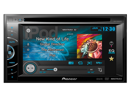
AVH-X3600BHS Bypass Radio Pioneer
If you find any conflicting info please leave a comment with what you found with your AVH X3600BHS AVH-X3600BHS radio. If you don’t see the audio radio wiring diagram you need comment and we will try to add it ASAP. Thanks for looking!
EASY INSTALL AND NO PROGRAMMING REQUIRED!
VERY SMALL IN SIZE!
USE THE MICRO BYPASS USED BELOW:
Easy to install 3-wire hookup and works great! Very small in size easy to hide.
Here is the info for bypassing the parking brake lockout on the Pioneer AVH-X2600BT radio. It will be useful when installing an aftermarket radio, sound stereo system, or other automotive accessories. Make sure to grab the appropriate tools to test all the wires. Please check it over and use it as a GUIDE to help you locate the appropriate wires. This schematic is provided free of charge and may not be 100% accurate. Failure to properly test all the wires may lead to vehicle or bodily damage. All information is provided as-is and accuracy is not guaranteed. This information is provided for informational purposes only and should not be used while driving.
Pioneer AVH-X2600BT Bypass Radio Parking Brake Break Override
If you find any conflicting info please leave a comment with what you found with your AVH X2600BT AVH-X2600BT. If you don’t see the audio radio wiring diagram you need comment and we will try to add it ASAP. Thanks for looking!
EASIEST INSTALL AND NO PROGRAMMING REQUIRED!
USE THE MICRO BYPASS USED BELOW:
Easy to install 3-wire hookup and works great! Very small in size easy to hide.
Here is the info for bypassing the parking brake lockout on the Pioneer AVH-X1600DVD radio. It will be useful when installing an aftermarket radio, sound stereo system, or other automotive accessories. Make sure to grab the appropriate tools to test all the wires. Please check it over and use it as a GUIDE to help you locate the appropriate wires. This schematic is provided free of charge and may not be 100% accurate. Failure to properly test all the wires may lead to vehicle or bodily damage. All information is provided as-is and accuracy is not guaranteed. This information is provided for informational purposes only and should not be used while driving.
Pioneer AVH-X1600DVD Bypass Radio Parking Brake Break Override
If you find any conflicting info please leave a comment with what you found with your AVH X1600DVD AVH-X1600DVD. If you don’t see the audio radio wiring diagram you need comment and we will try to add it ASAP. Thanks for looking!
EASIEST INSTALL AND NO PROGRAMMING REQUIRED!
USE THE MICRO BYPASS USED BELOW:
Easy to install 3-wire hookup and works great! Very small in size easy to hide.
Here is the stereo radio wiring information for your 2013 Chrysler 200 with the standard or amplified systems. It will be useful when installing an aftermarket radio, sound stereo system, or other automotive accessories. Make sure to grab the appropriate tools to test all the wires in your 200. Please check it over and use it as a GUIDE to help you locate the appropriate wires. This schematic is provided free of charge and may not be 100% accurate. Failure to properly test all the wires may lead to vehicle or bodily damage. All information is provided as-is and accuracy is not guaranteed.
2013 Chrysler 200 Audio Radio Wiring Diagram
If you find any conflicting info please leave a comment with what you found in your 2013 Chrysler 200. If you don’t see the audio radio wiring diagram you need comment and we will try to add it ASAP. Thanks for looking!
(MAKE SURE TO SCROLL TO THE BOTTOM TO SEE IF ANY OTHER READERS POSTED ANY OTHER TIPS AND TRICKS!)
2013 Chrysler 200 Audio Wiring Radio Diagram Schematic Colors
Car Radio Constant 12v+ Wire: Red/Brown @ Pin 1 Car Stereo Ground Wire: Black – Pin 12 Car Radio Ignition Switched Wire: @ Cigarette Lighter or Interface
Car Stereo VSS Speed Wire: N/A Car Stereo Reverse Wire + : White/Green (+) @ Light Car Stereo Dimmer Wire: N/A Car Radio Illumination Wire: White/Purple (Parking Lights) @ Driver kick Car Stereo Power Antenna: Gray/Orange (+) @ Pin 7 Car Radio Amp Turn On Wire: N/A
Left Front Speaker Wire (+) Positive: Gray/Purple – Pin 21 Left Front Speaker Wire (-) Negative: Gray/Yellow – Pin 22 Right Front Speaker Wire (+) Positive: Dark Green/Purple – Pin 19 Right Front Speaker Wire (-) Negative: Dark Green/Yellow – Pin 20
Left Rear Speaker Wire (+) Positive: Dark Green/Tan – Pin 8 Left Rear Speaker Wire (-) Negative: Dark Green/Gray – Pin 9 Right Rear Speaker Wire (+) Positive: Dark Green/Brown – Pin 10 Right Rear Speaker Wire (-) Negative: Yellow/Gray – Pin 11
Center Channel Speaker Wire Positive / Negative: N/A
Use the adapters below to install common 6.5″ speakers in the doors.
Check out these Infinity Kappa 6 x 9’s
they work great and are an excellent bang for the buck if you want to replace and upgrade your door speakers.
Radio Removal: Using plastic bezel removal tools carefully pop the radio bezel from the dash. Unplug all the connectors and remove the dash bezel. The radio and pocket below is then held in with 4 torx screws.
Keep in mind if you are installing a new radio you need the mounting kit, the wiring harness, the antenna adapter, and the steering wheel control adapter if you have audio controls on the wheel you want to keep.
REQUIRED PARTS FOR AFTERMARKET RADIO INSTALL
BASIC ECONOMY WIRING HARNESS WITHOUT OEM AMPLIFIED SYSTEM:
You will need to run the switched turn on from your radio to a ignition source but this harness will work great otherwise. See the other options below to save some time on the install!
ADVANCED WIRING HARNESS WITHOUT OEM AMPLIFIED SYSTEM:
Will provide switch turn on ignition lead, illumination and nav outputs like park brake, speed VSS, backup reverse wire, etc.
WIRING HARNESS WITH OEM AMPLIFIED SYSTEM:
Will also provide switch ignition power and nav outputs like parking brake, VSS speed, reverse wire, etc.
ANTENNA ADAPTER FOR INSTALL:
MOUNTING KIT FOR DOUBLE DIN AFTERMARKET RADIOS:
MOUNTING KIT FOR SINGLE DIN AFTERMARKET RADIOS:
CUSTOM UNDER SEAT BOX ENCLOSURE FOR ADDING AFTERMARKET SUB WOOFER:
Not available use a basic box like seen below to save on space and get plenty of bass!
SPEAKER WIRING ADAPTER FOR INSTALL:
Use these if you don’t want to tap in or cut off your existing speaker connectors. They plug right in then right on to the new speaker making installation a breeze. Order quantity 2 if doing front and rear speakers.
STEERING WHEEL CONTROLS ADAPTER:
Use this to retain the use of your OEM audio steering wheel controls with your new aftermarket radio. Works great easy wiring and simple programming.
Here is the stereo radio wiring information for your 2014 Chrysler 200 with the standard or amplified systems. It will be useful when installing an aftermarket radio, sound stereo system, or other automotive accessories. Make sure to grab the appropriate tools to test all the wires in your 200. Please check it over and use it as a GUIDE to help you locate the appropriate wires. This schematic is provided free of charge and may not be 100% accurate. Failure to properly test all the wires may lead to vehicle or bodily damage. All information is provided as-is and accuracy is not guaranteed.
2014 Chrysler 200 Audio Radio Wiring Diagram
If you find any conflicting info please leave a comment with what you found in your 2014 Chrysler 200. If you don’t see the audio radio wiring diagram you need comment and we will try to add it ASAP. Thanks for looking!
(MAKE SURE TO SCROLL TO THE BOTTOM TO SEE IF ANY OTHER READERS POSTED ANY OTHER TIPS AND TRICKS!)
2014 Chrysler 200 Audio Wiring Radio Diagram Schematic Colors
Car Radio Constant 12v+ Wire: Red/Brown @ Pin 1 Car Stereo Ground Wire: Black – Pin 12 Car Radio Ignition Switched Wire: @ Cigarette Lighter or Interface
Car Stereo VSS Speed Wire: N/A Car Stereo Reverse Wire + : White/Green (+) @ Light Car Stereo Dimmer Wire: N/A Car Radio Illumination Wire: White/Purple (Parking Lights) @ Driver kick Car Stereo Power Antenna: Gray/Orange (+) @ Pin 7 Car Radio Amp Turn On Wire: N/A
Left Front Speaker Wire (+) Positive: Gray/Purple – Pin 21 Left Front Speaker Wire (-) Negative: Gray/Yellow – Pin 22 Right Front Speaker Wire (+) Positive: Dark Green/Purple – Pin 19 Right Front Speaker Wire (-) Negative: Dark Green/Yellow – Pin 20
Left Rear Speaker Wire (+) Positive: Dark Green/Tan – Pin 8 Left Rear Speaker Wire (-) Negative: Dark Green/Gray – Pin 9 Right Rear Speaker Wire (+) Positive: Dark Green/Brown – Pin 10 Right Rear Speaker Wire (-) Negative: Yellow/Gray – Pin 11
Center Channel Speaker Wire Positive / Negative: N/A
Use the adapters below to install common 6.5″ speakers in the doors.
Check out these Infinity Kappa 6 x 9’s
they work great and are an excellent bang for the buck if you want to replace and upgrade your door speakers.
Radio Removal: Using plastic bezel removal tools carefully pop the radio bezel from the dash. Unplug all the connectors and remove the dash bezel. The radio and pocket below is then held in with 4 torx screws.
Keep in mind if you are installing a new radio you need the mounting kit, the wiring harness, the antenna adapter, and the steering wheel control adapter if you have audio controls on the wheel you want to keep.
REQUIRED PARTS FOR AFTERMARKET RADIO INSTALL
BASIC ECONOMY WIRING HARNESS WITHOUT OEM AMPLIFIED SYSTEM:
You will need to run the switched turn on from your radio to a ignition source but this harness will work great otherwise. See the other options below to save some time on the install!
ADVANCED WIRING HARNESS WITHOUT OEM AMPLIFIED SYSTEM:
Will provide switch turn on ignition lead, illumination and nav outputs like park brake, speed VSS, backup reverse wire, etc.
WIRING HARNESS WITH OEM AMPLIFIED SYSTEM:
Will also provide switch ignition power and nav outputs like parking brake, VSS speed, reverse wire, etc.
ANTENNA ADAPTER FOR INSTALL:
MOUNTING KIT FOR DOUBLE DIN AFTERMARKET RADIOS:
MOUNTING KIT FOR SINGLE DIN AFTERMARKET RADIOS:
CUSTOM UNDER SEAT BOX ENCLOSURE FOR ADDING AFTERMARKET SUB WOOFER:
Not available use a basic box like seen below to save on space and get plenty of bass!
SPEAKER WIRING ADAPTER FOR INSTALL:
Use these if you don’t want to tap in or cut off your existing speaker connectors. They plug right in then right on to the new speaker making installation a breeze. Order quantity 2 if doing front and rear speakers.
STEERING WHEEL CONTROLS ADAPTER:
Use this to retain the use of your OEM audio steering wheel controls with your new aftermarket radio. Works great easy wiring and simple programming.
Here is the stereo radio wiring information for your 2006 Honda Ridgeline with the standard or amplified systems. It will be useful when installing an aftermarket radio, sound stereo system, or other automotive accessories. Make sure to grab the appropriate tools to test all the wires in your Ridgeline. Please check it over and use it as a GUIDE to help you locate the appropriate wires. This schematic is provided free of charge and may not be 100% accurate. Failure to properly test all the wires may lead to vehicle or bodily damage. All information is provided as-is and accuracy is not guaranteed.
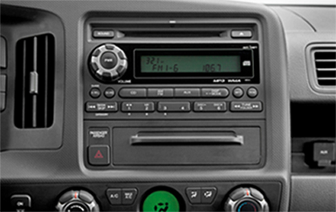
2006 Honda Ridgeline Audio Wiring Radio
If you find any conflicting info please leave a comment with what you found in your 2006 Honda Ridgeline. If you don’t see the audio radio wiring diagram you need comment and we will try to add it ASAP. Thanks for looking!
(MAKE SURE TO SCROLL TO THE BOTTOM TO SEE IF ANY OTHER READERS POSTED ANY OTHER TIPS AND TRICKS!)
2006 Honda Ridgeline Audio Wiring Radio Diagram Schematic Colors
Car Radio Constant 12v+ Wire: White – Pin 10 Car Stereo Ground Wire: Black – Pin 20 Car Radio Ignition Switched Wire: Yellow/Red Pin 2 @ Radio Harness
Car Stereo VSS Speed Wire: N/A Car Stereo Reverse Wire + : Green (+) @ Light Car Stereo Dimmer Wire: Red @ Pin 19 Car Radio Illumination Wire: Red/Black (Parking Lights) @ Pin 9 Car Stereo Power Antenna: Black (+) Pin 3 @ Antenna Plug Car Radio Amp Turn On Wire: N/A
Left Front Speaker Wire (+) Positive: Light Green – Pin 8 Left Front Speaker Wire (-) Negative: Violet – Pin 18 Right Front Speaker Wire (+) Positive: Blue – Pin 7 Right Front Speaker Wire (-) Negative: Red – Pin 17
Left Rear Speaker Wire (+) Positive: Brown/White – Pin 6 Left Rear Speaker Wire (-) Negative: Red/Yellow – Pin 16 Right Rear Speaker Wire (+) Positive: Red/Blue – Pin 5 Right Rear Speaker Wire (-) Negative: Yellow – Pin 15
Center Channel Speaker Wire Positive / Negative: N/A
These wires let you keep your OEM aux jack to work with your new aftermarket radio. Grab a cheap RCA Auxiliary Cable plug either the aux or the rcas into the back of your new aftermarket radio depending on what type of audio input they have. Then cut off the other end and splice into the following wires at the 14-pin connector found behind the radio:
OEM AUX Audio Left Signal: White @ 6 pin connector pin 5 OEM AUX Audio Left Ground: Red @ 6 pin connector pin 4 OEM AUX Audio Right Signal: Brown @ 6 pin connector pin 3 OEM AUX Audio Right Ground Red @ 6 pin connector pin 4
Use the adapters below to install common 6.5″ speakers in the doors. Depending on the size and depth of speakers you still may need to cut some of the door metal away. Use some tin snips to easily get the job done.
Radio Removal: Using plastic bezel removal tools carefully pop the radio bezel from the dash. Unplug all the connectors and remove the dash bezel. The radio and pocket below is then held in with 5 screws.
Keep in mind if you are installing a new radio you need the mounting kit, the wiring harness, the antenna adapter, and the steering wheel control adapter if you have audio controls on the wheel you want to keep.
REQUIRED PARTS FOR AFTERMARKET RADIO INSTALL
WIRING HARNESS:
ANTENNA ADAPTER FOR INSTALL:
GRAY MOUNTING KIT FOR DOUBLE DIN AFTERMARKET RADIOS:
TAN MOUNTING KIT FOR DOUBLE DIN AFTERMARKET RADIOS:
GRAY MOUNTING KIT FOR SINGLE DIN AFTERMARKET RADIOS:
TAN MOUNTING KIT FOR SINGLE DIN AFTERMARKET RADIOS:
CUSTOM UNDER SEAT BOX ENCLOSURE FOR ADDING AFTERMARKET SUB WOOFER:
SPEAKER WIRING ADAPTER FOR INSTALL:
Use these if you don’t want to tap in or cut off your existing speaker connectors. They plug right in then right on to the new speaker making installation a breeze. Order quantity 2 if doing front and rear speakers.
Here is the stereo radio wiring information for your 2007 Honda Ridgeline with the standard or amplified systems. It will be useful when installing an aftermarket radio, sound stereo system, or other automotive accessories. Make sure to grab the appropriate tools to test all the wires in your Ridgeline. Please check it over and use it as a GUIDE to help you locate the appropriate wires. This schematic is provided free of charge and may not be 100% accurate. Failure to properly test all the wires may lead to vehicle or bodily damage. All information is provided as-is and accuracy is not guaranteed.
2007 Honda RIdgeline Audio Radio Wiring DIagram
If you find any conflicting info please leave a comment with what you found in your 2007 Honda Ridgeline. If you don’t see the audio radio wiring diagram you need comment and we will try to add it ASAP. Thanks for looking!
(MAKE SURE TO SCROLL TO THE BOTTOM TO SEE IF ANY OTHER READERS POSTED ANY OTHER TIPS AND TRICKS!)
2007 Honda Ridgeline Audio Wiring Radio Diagram Schematic Colors
Car Radio Constant 12v+ Wire: White – Pin 10 Car Stereo Ground Wire: Black – Pin 20 Car Radio Ignition Switched Wire: Yellow/Red Pin 2 @ Radio Harness
Car Stereo VSS Speed Wire: N/A Car Stereo Reverse Wire + : Green (+) @ Light Car Stereo Dimmer Wire: Red @ Pin 19 Car Radio Illumination Wire: Red/Black (Parking Lights) @ Pin 9 Car Stereo Power Antenna: Black (+) Pin 3 @ Antenna Plug Car Radio Amp Turn On Wire: N/A
Left Front Speaker Wire (+) Positive: Light Green – Pin 8 Left Front Speaker Wire (-) Negative: Violet – Pin 18 Right Front Speaker Wire (+) Positive: Blue – Pin 7 Right Front Speaker Wire (-) Negative: Red – Pin 17
Left Rear Speaker Wire (+) Positive: Brown/White – Pin 6 Left Rear Speaker Wire (-) Negative: Red/Yellow – Pin 16 Right Rear Speaker Wire (+) Positive: Red/Blue – Pin 5 Right Rear Speaker Wire (-) Negative: Yellow – Pin 15
Center Channel Speaker Wire Positive / Negative: N/A
These wires let you keep your OEM aux jack to work with your new aftermarket radio. Grab a cheap RCA Auxiliary Cable plug either the aux or the rcas into the back of your new aftermarket radio depending on what type of audio input they have. Then cut off the other end and splice into the following wires at the 14-pin connector found behind the radio:
OEM AUX Audio Left Signal: White @ 6 pin connector pin 5 OEM AUX Audio Left Ground: Red @ 6 pin connector pin 4 OEM AUX Audio Right Signal: Brown @ 6 pin connector pin 3 OEM AUX Audio Right Ground Red @ 6 pin connector pin 4
Use the adapters below to install common 6.5″ speakers in the doors. Depending on the size and depth of speakers you still may need to cut some of the door metal away. Use some tin snips to easily get the job done.
Radio Removal: Using plastic bezel removal tools carefully pop the radio bezel from the dash. Unplug all the connectors and remove the dash bezel. The radio and pocket below is then held in with 5 screws.
Keep in mind if you are installing a new radio you need the mounting kit, the wiring harness, the antenna adapter, and the steering wheel control adapter if you have audio controls on the wheel you want to keep.
REQUIRED PARTS FOR AFTERMARKET RADIO INSTALL
WIRING HARNESS:
ANTENNA ADAPTER FOR INSTALL:
GRAY MOUNTING KIT FOR DOUBLE DIN AFTERMARKET RADIOS:
TAN MOUNTING KIT FOR DOUBLE DIN AFTERMARKET RADIOS:
GRAY MOUNTING KIT FOR SINGLE DIN AFTERMARKET RADIOS:
TAN MOUNTING KIT FOR SINGLE DIN AFTERMARKET RADIOS:
CUSTOM UNDER SEAT BOX ENCLOSURE FOR ADDING AFTERMARKET SUB WOOFER:
SPEAKER WIRING ADAPTER FOR INSTALL:
Use these if you don’t want to tap in or cut off your existing speaker connectors. They plug right in then right on to the new speaker making installation a breeze. Order quantity 2 if doing front and rear speakers.
Here is the stereo radio wiring information for your 2008 Honda Ridgeline with the standard or amplified systems. It will be useful when installing an aftermarket radio, sound stereo system, or other automotive accessories. Make sure to grab the appropriate tools to test all the wires in your Ridgeline. Please check it over and use it as a GUIDE to help you locate the appropriate wires. This schematic is provided free of charge and may not be 100% accurate. Failure to properly test all the wires may lead to vehicle or bodily damage. All information is provided as-is and accuracy is not guaranteed.
2008 Honda Ridgeline Audio Radio Wiring
If you find any conflicting info please leave a comment with what you found in your 2008 Honda Ridgeline. If you don’t see the audio radio wiring diagram you need comment and we will try to add it ASAP. Thanks for looking!
(MAKE SURE TO SCROLL TO THE BOTTOM TO SEE IF ANY OTHER READERS POSTED ANY OTHER TIPS AND TRICKS!)
2008 Honda Ridgeline Audio Wiring Radio Diagram Schematic Colors
Car Radio Constant 12v+ Wire: White – Pin 10 Car Stereo Ground Wire: Black – Pin 20 Car Radio Ignition Switched Wire: Yellow/Red Pin 2 @ Radio Harness
Car Stereo VSS Speed Wire: N/A Car Stereo Reverse Wire + : Green (+) @ Light Car Stereo Dimmer Wire: Red @ Pin 19 Car Radio Illumination Wire: Red/Black (Parking Lights) @ Pin 9 Car Stereo Power Antenna: Black (+) Pin 3 @ Antenna Plug Car Radio Amp Turn On Wire: N/A
Left Front Speaker Wire (+) Positive: Light Green – Pin 8 Left Front Speaker Wire (-) Negative: Violet – Pin 18 Right Front Speaker Wire (+) Positive: Blue – Pin 7 Right Front Speaker Wire (-) Negative: Red – Pin 17
Left Rear Speaker Wire (+) Positive: Brown/White – Pin 6 Left Rear Speaker Wire (-) Negative: Red/Yellow – Pin 16 Right Rear Speaker Wire (+) Positive: Red/Blue – Pin 5 Right Rear Speaker Wire (-) Negative: Yellow – Pin 15
Center Channel Speaker Wire Positive / Negative: N/A
These wires let you keep your OEM aux jack to work with your new aftermarket radio. Grab a cheap RCA Auxiliary Cable plug either the aux or the rcas into the back of your new aftermarket radio depending on what type of audio input they have. Then cut off the other end and splice into the following wires at the 14-pin connector found behind the radio:
OEM AUX Audio Left Signal: White @ 6 pin connector pin 5 OEM AUX Audio Left Ground: Red @ 6 pin connector pin 4 OEM AUX Audio Right Signal: Brown @ 6 pin connector pin 3 OEM AUX Audio Right Ground Red @ 6 pin connector pin 4
Use the adapters below to install common 6.5″ speakers in the doors. Depending on the size and depth of speakers you still may need to cut some of the door metal away. Use some tin snips to easily get the job done.
Radio Removal: Using plastic bezel removal tools carefully pop the radio bezel from the dash. Unplug all the connectors and remove the dash bezel. The radio and pocket below is then held in with 5 screws.
Keep in mind if you are installing a new radio you need the mounting kit, the wiring harness, the antenna adapter, and the steering wheel control adapter if you have audio controls on the wheel you want to keep.
REQUIRED PARTS FOR AFTERMARKET RADIO INSTALL
WIRING HARNESS:
ANTENNA ADAPTER FOR INSTALL:
GRAY MOUNTING KIT FOR DOUBLE DIN AFTERMARKET RADIOS:
TAN MOUNTING KIT FOR DOUBLE DIN AFTERMARKET RADIOS:
GRAY MOUNTING KIT FOR SINGLE DIN AFTERMARKET RADIOS:
TAN MOUNTING KIT FOR SINGLE DIN AFTERMARKET RADIOS:
CUSTOM UNDER SEAT BOX ENCLOSURE FOR ADDING AFTERMARKET SUB WOOFER:
SPEAKER WIRING ADAPTER FOR INSTALL:
Use these if you don’t want to tap in or cut off your existing speaker connectors. They plug right in then right on to the new speaker making installation a breeze. Order quantity 2 if doing front and rear speakers.
Here is the stereo radio wiring information for your 2009 Honda Ridgeline with the standard or amplified systems. It will be useful when installing an aftermarket radio, sound stereo system, or other automotive accessories. Make sure to grab the appropriate tools to test all the wires in your Ridgeline. Please check it over and use it as a GUIDE to help you locate the appropriate wires. This schematic is provided free of charge and may not be 100% accurate. Failure to properly test all the wires may lead to vehicle or bodily damage. All information is provided as-is and accuracy is not guaranteed.
2009 Honda RIdgeline Radio Audio Wiring
If you find any conflicting info please leave a comment with what you found in your 2009 Honda Ridgeline. If you don’t see the audio radio wiring diagram you need comment and we will try to add it ASAP. Thanks for looking!
(MAKE SURE TO SCROLL TO THE BOTTOM TO SEE IF ANY OTHER READERS POSTED ANY OTHER TIPS AND TRICKS!)
2009 Honda Ridgeline Audio Wiring Radio Diagram Schematic Colors
Car Radio Constant 12v+ Wire: White – Pin 24 Car Stereo Ground Wire: Black – Pin 12 Car Radio Ignition Switched Wire: Yellow/Red Pin 14 @ Radio Harness
Car Stereo VSS Speed Wire: N/A Car Stereo Reverse Wire + : Green (+) @ Light Car Stereo Dimmer Wire: Red @ Pin 1 Car Radio Illumination Wire: Red/Black (Parking Lights) @ Pin 13 Car Stereo Power Antenna: Black (+) Pin 3 @ Antenna Plug Car Radio Amp Turn On Wire: N/A
Left Front Speaker Wire (+) Positive: Light Green – Pin 23 Left Front Speaker Wire (-) Negative: Violet – Pin 22 Right Front Speaker Wire (+) Positive: Blue – Pin 19 Right Front Speaker Wire (-) Negative: Red – Pin 18
Left Rear Speaker Wire (+) Positive: Brown/White – Pin 11 Left Rear Speaker Wire (-) Negative: Red/Yellow – Pin 10 Right Rear Speaker Wire (+) Positive: Red/Blue – Pin 7 Right Rear Speaker Wire (-) Negative: Yellow – Pin 6
Center Channel Speaker Wire Positive / Negative: N/A
These wires let you keep your OEM aux jack to work with your new aftermarket radio. Grab a cheap RCA Auxiliary Cable plug either the aux or the rcas into the back of your new aftermarket radio depending on what type of audio input they have. Then cut off the other end and splice into the following wires at the 14-pin connector found behind the radio:
OEM AUX Audio Left Signal: White @ 14 pin connector pin 1 OEM AUX Audio Left Ground: Red @ 14 pin connector pin 2 OEM AUX Audio Right Signal: Brown @ 14 pin connector pin 8 OEM AUX Audio Right Ground Red @ 14 pin connector pin 2
Use the adapters below to install common 6.5″ speakers in the doors. Depending on the size and depth of speakers you still may need to cut some of the door metal away. Use some tin snips to easily get the job done.
Radio Removal: Using plastic bezel removal tools carefully pop the radio bezel from the dash. Unplug all the connectors and remove the dash bezel. The radio and pocket below is then held in with 5 screws.
Keep in mind if you are installing a new radio you need the mounting kit, the wiring harness, the antenna adapter, and the steering wheel control adapter if you have audio controls on the wheel you want to keep.
REQUIRED PARTS FOR AFTERMARKET RADIO INSTALL
WIRING HARNESS:
GRAY MOUNTING KIT FOR DOUBLE DIN AFTERMARKET RADIOS:
TAN MOUNTING KIT FOR DOUBLE DIN AFTERMARKET RADIOS:
GRAY MOUNTING KIT FOR SINGLE DIN AFTERMARKET RADIOS:
TAN MOUNTING KIT FOR SINGLE DIN AFTERMARKET RADIOS:
ANTENNA ADAPTER FOR INSTALL:
CUSTOM UNDER SEAT BOX ENCLOSURE FOR ADDING AFTERMARKET SUB WOOFER:
SPEAKER WIRING ADAPTER FOR INSTALL:
Use these if you don’t want to tap in or cut off your existing speaker connectors. They plug right in then right on to the new speaker making installation a breeze. Order quantity 2 if doing front and rear speakers.
Here is the stereo radio wiring information for your 2010 Honda Ridgeline with the standard or amplified systems. It will be useful when installing an aftermarket radio, sound stereo system, or other automotive accessories. Make sure to grab the appropriate tools to test all the wires in your Ridgeline. Please check it over and use it as a GUIDE to help you locate the appropriate wires. This schematic is provided free of charge and may not be 100% accurate. Failure to properly test all the wires may lead to vehicle or bodily damage. All information is provided as-is and accuracy is not guaranteed.
2010 Honda RIdgeline Audio Radio WIring
If you find any conflicting info please leave a comment with what you found in your 2011 Honda Ridgeline. If you don’t see the audio radio wiring diagram you need comment and we will try to add it ASAP. Thanks for looking!
(MAKE SURE TO SCROLL TO THE BOTTOM TO SEE IF ANY OTHER READERS POSTED ANY OTHER TIPS AND TRICKS!)
2010 Honda Ridgeline Audio Wiring Radio Diagram Schematic Colors
Car Radio Constant 12v+ Wire: White – Pin 24 Car Stereo Ground Wire: Black – Pin 12 Car Radio Ignition Switched Wire: Yellow/Red Pin 14 @ Radio Harness
Car Stereo VSS Speed Wire: N/A Car Stereo Reverse Wire + : Green (+) @ Light Car Stereo Dimmer Wire: Red @ Pin 1 Car Radio Illumination Wire: Red/Black (Parking Lights) @ Pin 13 Car Stereo Power Antenna: Black (+) Pin 3 @ Antenna Plug Car Radio Amp Turn On Wire: N/A
Left Front Speaker Wire (+) Positive: Light Green – Pin 23 Left Front Speaker Wire (-) Negative: Violet – Pin 22 Right Front Speaker Wire (+) Positive: Blue – Pin 19 Right Front Speaker Wire (-) Negative: Red – Pin 18
Left Rear Speaker Wire (+) Positive: Brown/White – Pin 11 Left Rear Speaker Wire (-) Negative: Red/Yellow – Pin 10 Right Rear Speaker Wire (+) Positive: Red/Blue – Pin 7 Right Rear Speaker Wire (-) Negative: Yellow – Pin 6
Center Channel Speaker Wire Positive / Negative: N/A
These wires let you keep your OEM aux jack to work with your new aftermarket radio. Grab a cheap RCA Auxiliary Cable plug either the aux or the rcas into the back of your new aftermarket radio depending on what type of audio input they have. Then cut off the other end and splice into the following wires at the 14-pin connector found behind the radio:
OEM AUX Audio Left Signal: White @ 14 pin connector pin 1 OEM AUX Audio Left Ground: Red @ 14 pin connector pin 2 OEM AUX Audio Right Signal: Brown @ 14 pin connector pin 8 OEM AUX Audio Right Ground Red @ 14 pin connector pin 2
Use the adapters below to install common 6.5″ speakers in the doors. Depending on the size and depth of speakers you still may need to cut some of the door metal away. Use some tin snips to easily get the job done.
Radio Removal: Using plastic bezel removal tools carefully pop the radio bezel from the dash. Unplug all the connectors and remove the dash bezel. The radio and pocket below is then held in with 5 screws.
Keep in mind if you are installing a new radio you need the mounting kit, the wiring harness, the antenna adapter, and the steering wheel control adapter if you have audio controls on the wheel you want to keep.
REQUIRED PARTS FOR AFTERMARKET RADIO INSTALL
WIRING HARNESS:
GRAY MOUNTING KIT FOR DOUBLE DIN AFTERMARKET RADIOS:
TAN MOUNTING KIT FOR DOUBLE DIN AFTERMARKET RADIOS:
GRAY MOUNTING KIT FOR SINGLE DIN AFTERMARKET RADIOS:
TAN MOUNTING KIT FOR SINGLE DIN AFTERMARKET RADIOS:
ANTENNA ADAPTER FOR INSTALL:
CUSTOM UNDER SEAT BOX ENCLOSURE FOR ADDING AFTERMARKET SUB WOOFER:
SPEAKER WIRING ADAPTER FOR INSTALL:
Use these if you don’t want to tap in or cut off your existing speaker connectors. They plug right in then right on to the new speaker making installation a breeze. Order quantity 2 if doing front and rear speakers.