Tag Archives: amp

2006 Jeep Grand Cherokee Audio Wiring Diagram Radio Colors

Here is the stereo radio wiring information for your 2006 Jeep Grand Cherokee WK body with the standard, symphony, or Bose systems. It will be useful when installing an aftermarket radio, sound stereo system, or other automotive accessories. Make sure to grab the appropriate tools to test all the wires in your Grand Cherokee. Please check it over and use it as a GUIDE to help you locate the appropriate wires. This schematic is provided free of charge and may not be 100% accurate. Failure to properly test all the wires may lead to vehicle or bodily damage. All information is provided as-is and accuracy is not guaranteed.

2006 Grand Cherokee Audio Wiring Diagram

If you find any conflicting info please leave a comment with what you found in your WK Grand Cherokee. If you don’t see the audio wiring diagram you need comment and we will try to add it ASAP. Thanks for looking!

2006 Jeep Grand Cherokee Radio Wiring Diagram Audio Schematic Colors

Car Radio Constant 12v+ Wire: Red/Orange
Car Stereo Ground Wire: Black
Car Radio Ignition Switched Wire: N/A DATA – Red/Light Green or Pink/Yellow or Pink/Green @ Power Port

Car Stereo Dimmer Wire: Orange/Brown @ Climate Control Connector
Car Radio Illumination Wire: N/A DATA
Car Stereo Power Antenna:
Car Radio Amp Turn On Wire: N/A DATA

Left Front Speaker Wire (+) Positive: Gray/Orange
Left Front Speaker Wire (-) Negative: Gray/Yellow
Right Front Speaker Wire (+) Positive: Gray/Dark Green
Right Front Speaker Wire (-) Negative: Gray/Light Green

Left Rear Speaker Wire (+) Positive: Dark Green/Dark Blue
Left Rear Speaker Wire (-) Negative: Dark Green/Purple
Right Rear Speaker Wire (+) Positive: Gray/Dark Blue
Right Rear Speaker Wire (-) Negative: Gray/Tan

Center Channel Speaker Wire Positive / Negative:

Subwoofer Speaker Wire Positive / Negative:

SPEAKER WIRE COLORS AT THE SPEAKERS

Driver Door Pos + : Gray/Purple or Dark Green/Purple
Driver Door Neg – : Gray/Yellow or Dark Green/Yellow

Passenger Door Pos + : Dark Green/Purple
Passenger Door Neg – : Gray/Yellow or Dark Green/Yellow

LR Left Rear Door Pos + : Gray/Light Green or Dark Green/Light Green
LR Left Rear Door Neg – : Gray/Dark Green or Light Green/Gray

RR Right Rear Door Pos + : Gray/Light Green or Dark Green/Light Green
RR Right Rear Door Neg – : Gray/Dark Green or Light Green/Gray

Front Speaker Size: 6×9″ Front Doors

Upper Dash Speaker Size: 3.5″

Rear Speaker Size: 6.5″ Rear Doors

Amp Amplifier Location: Cargo Area Behind Trim
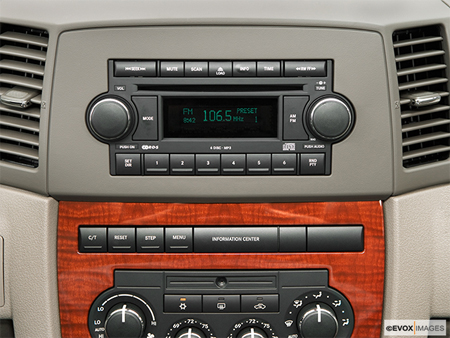
Radio Size: 1.5 Din

Radio Removal: The panel around the radio is only held on by clips just use these pry tools and carefully pry it off. It may be tight if it was never removed before. Once removed the radio is secured with 4 Phillips screws.

Keep in mind if you are installing a new radio you may need the radio removal keys, the wiring harness, the antenna adapter, and the mounting kit as well.

REQUIRED PARTS FOR AFTERMARKET RADIO INSTALL

PACKAGE: DOUBLE DIN INSTALL NON AMPED SYSTEM INCLUDES ALL PARTS GRAY COLOR: Jeep Grand Cherokee 2005-2007 Double Din Navigation Radio Bezel Dash Install Kit with Standard Wiring Harness and Antenna Adapter – GREY

PACKAGE: DOUBLE DIN INSTALL NON AMPED SYSTEM INCLUDES ALL PARTS KHAKI COLOR:
Jeep Grand Cherokee 2005-2007 Double Din Navigation Radio Bezel Dash Install Kit with Standard Wiring Harness and Antenna Adapter – KHAKI

WIRING HARNESS FOR NON AMPLIFIED:
Metra 70-6502 Radio Wiring Harness For Chrysler 02-Up Power 4 Speaker

WIRING INTERFACE FOR AMPLIFIED SYSTEM:
Axxess CHTO-01 Chrysler CAN Amp Turn-On Adapter

MOUNTING KIT FOR SINGLE DIN AFTERMARKET RADIOS:
Metra 99-6507 Single DIN Installation Kit for Select 2004-2008 Chrysler/Dodge/Jeep Vehicles

MOUNTING KIT FOR DOUBLE DIN AFTERMARKET RADIOS: ** REQUIRES OEM NAV BEZEL ** Metra 99-6510 Chry/Dodge/Jeep with NAV 04-UP Dash Kit

ANTENNA ADAPTER FOR INSTALL:
Metra 40-CR10 Chrysler 2002 Antenna Adapter Cable

RECOMMENDED TOOLS FOR THE INSTALL – SAME ONES THE PROS USE!

– Klein Wire Cutters / Crimpers

– Gardner Bender Auto Wire Stripper

– Dash Removal Plastic Pry Tools

– 3M Electrical Tape

– Install Bay Butt Connectors

2015 Chrysler 200 Car Radio Audio Stereo Wiring Diagram Colors

Here is the stereo radio wiring information for your 2015 Chrysler 200 with the standard, premium,  symphony, or Bose systems. It will be useful when installing an aftermarket radio, sound stereo system, or other automotive accessories. Make sure to grab the appropriate tools to test all the wires in your 200. Please check it over and use it as a GUIDE to help you locate the appropriate wires. This schematic is provided free of charge and may not be 100% accurate. Failure to properly test all the wires may lead to vehicle or bodily damage. All information is provided as-is and accuracy is not guaranteed.

2015 Chrysler 200 audio wiring diagram radio

If you find any conflicting info please leave a comment with what you found in your Chrysler 200. If you don’t see the wiring diagram you need comment and we will try to add it ASAP. Thanks for looking!

2015 Chrysler 200 Car Audio Stereo Radio Wiring Diagram Schematic Colors

Car Radio Constant 12v+ Wire: Red
Car Stereo Ground Wire: Black
Car Radio Ignition Switched Wire: N/A CAN

Car Stereo Dimmer Wire: N/A CAN
Car Radio Illumination Wire:
Car Stereo Power Antenna:
Car Radio Amp Turn On Wire:

Left Front Speaker Wire (+) Positive: Gray/Purple @ Back of Radio
Left Front Speaker Wire (-) Negative: Gray/Yellow
Right Front Speaker Wire (+) Positive: Dark Green/Purple
Right Front Speaker Wire (-) Negative: Dark Green/Yellow

Left Rear Speaker Wire (+) Positive: Gray/Light Green
Left Rear Speaker Wire (-) Negative: Gray/Dark Green
Right Rear Speaker Wire (+) Positive: Dark Green/Light Green
Right Rear Speaker Wire (-) Negative: Dark Green/Gray

Center Channel Speaker Wire Positive / Negative: Gray/Brown & Gray/Orange @ Amp

Subwoofer Speaker Wire Positive / Negative: Gray/Brown & Dark Green Brown @ Amp

Subwoofer Speaker Wire Positive / Negative: Gray/White & Dark Green/White @ Amplifier

Front Speaker Size: N/A

Rear Speaker Size: N/A

Amp Amplifier Location: Passenger side behind glovebox

Radio Removal: See Service Manual

Keep in mind if you are installing a new radio you may need the radio removal  keys, the wiring harness, the antenna adapter, and the mounting kit as well. We always recommend using the appropriate interface adapters in case you want to reinstall your OEM radio later. See the links below to purchase these items.

RECOMMENDED TOOLS FOR THE INSTALL – SAME ONES THE PROS USE!

– Klein Wire Cutters / Crimpers

– Gardner Bender Auto Wire Stripper

– Dash Removal Plastic Pry Tools

– 3M Electrical Tape

– Install Bay Butt Connectors

2015 Chevrolet Tahoe Car Radio Audio Stereo Wiring Diagram Colors

Here is the stereo radio wiring information for your 2015 Chevrolet Tahoe with the standard, premium,  symphony, or Bose systems. It will be useful when installing an aftermarket radio, sound stereo system, or other automotive accessories. Make sure to grab the appropriate tools to test all the wires in your Tahoe. Please check it over and use it as a GUIDE to help you locate the appropriate wires. This schematic is provided free of charge and may not be 100% accurate. Failure to properly test all the wires may lead to vehicle or bodily damage. All information is provided as-is and accuracy is not guaranteed.

If you find any conflicting info please leave a comment with what you found in your Chevy Tahoe. If you don’t see the wiring diagram you need comment and we will try to add it ASAP. Thanks for looking!

2015 Chevrolet Tahoe Car Audio Stereo Radio Wiring Diagram Schematic Colors

Car Radio Constant 12v+ Wire: Red/Purple
Car Stereo Ground Wire: Black
Car Radio Ignition Switched Wire: N/A DATA

Car Stereo Dimmer Wire: N/A Data

Car Radio Illumination Wire:
Car Stereo Power Antenna:
Car Radio Amp Turn On Wire:

Left Front Speaker Wire (+) Positive: Blue
Left Front Speaker Wire (-) Negative: Brown/Blue
Right Front Speaker Wire (+) Positive: Yellow
Right Front Speaker Wire (-) Negative: Yellow/Black

Left Rear Speaker Wire (+) Positive: Green
Left Rear Speaker Wire (-) Negative: Green/Black
Right Rear Speaker Wire (+) Positive: White
Right Rear Speaker Wire (-) Negative: Blue/Black

Center Channel Speaker Wire Positive / Negative:

Subwoofer Speaker Wire Positive / Negative: Blue/Gray & Gray/Black

Front Speaker Size: N/A

Rear Speaker Size: N/A

Amp Amplifier Location: Back of Vehicle Behind Rear Seats

Radio Removal: See Service Manual

Keep in mind if you are installing a new radio you may need the radio removal  keys, the wiring harness, the antenna adapter, and the mounting kit as well. We always recommend using the appropriate interface adapters in case you want to reinstall your OEM radio later. See the links below to purchase these items.

1998 BMW E36 3-Series 328i Car Radio Audio Stereo Wiring Diagram Colors

Here is the stereo radio wiring information for your 1998 BMW 3-Series E36 328i with the standard, symphony, or Bose systems. It will be useful when installing an aftermarket radio, sound stereo system, or other automotive accessories. Make sure to grab the appropriate tools to test all the wires in your E36 328i BMW. Please check it over and use it as a GUIDE to help you locate the appropriate wires. This schematic is provided free of charge and may not be 100% accurate. Failure to properly test all the wires may lead to vehicle or bodily damage. All information is provided as-is and accuracy is not guaranteed.

If you find any conflicting info please leave a comment with what you found in your BMW 3-Series including the 328i. If you don’t see the wiring diagram you need comment and we will try to add it ASAP. Thanks for looking!

Keep in mind if you are installing a new radio you may need the radio removal  keys, the wiring harness, the antenna adapter, and the mounting kit as well. See the links below to purchase these items.

1998 BMW 3-Series E36 328i Car Audio Stereo Radio Wiring Diagram Schematic Colors

Car Radio Constant 12v+ Wire: Red/White
Car Stereo Ground Wire: Brown
Car Radio Ignition Switched Wire: Purple/White

Car Stereo Dimmer Wire:

Car Radio Illumination Wire:
Car Stereo Power Antenna:
Car Radio Amp Turn On Wire:  White +

** FOUND AT BACK OF RADIO OR AMP **

Left Front Low Level Ouput to Amp Wire (+) Positive: Yellow/Red
Left Front Low Level Output to Amp  Wire (-) Negative: Brown/Orange
Right Front  Low Level Output Speaker Wire (+) Positive: Blue/Red
Right Front Low Level Output Speaker Wire (-) Negative: Brown/Orange

Left Rear Low Level Output Speaker Wire (+) Positive: Yellow/Black
Left Rear Low Level Output Speaker Wire (-) Negative: Brown/Orange
Right Rear Low Level Output Speaker Wire (+) Positive: Blue/Black
Right Rear Low Level Output Speaker Wire (-) Negative: Brown/Orange

** FOUND AT AMP IN REAR **

LF Tweeter Speaker Wire (+) Positive: Yellow/Black

LF Tweeter Speaker Wire (-) Negative: Yellow/Brown

LF Front Left Mid Speaker Wire (+) Positive: Yellow/Red

LF Front Left Mid Speaker Wire (-) Negative: Yellow/Brown

RF Tweeter Speaker Wire (+) Positive: Blue/Green or Blue/Black

RF Tweeter Speaker Wire (-) Negative: Blue/Brown

RF Front Right Mid Speaker Wire (+) Positive: Blue/Red

RF Front Right Mid Speaker Wire (-) Negative: Blue/Brown

LR Rear Left Tweeter Speaker Wire (+) Positive: Yellow

LR Rear Left Tweeter Speaker Wire (-) Negative: Brown

RR Rear Right Tweeter Speaker Wire (+) Positive: Blue

RR Rear Right Tweeter Speaker Wire (-) Negative: Brown


LF Woofer Speaker Wire (+) Positive: Yellow / Red @ Amp Pin 7

LF Woofer Speaker Wire (-) Negative: Yellow / Brown Pin 8

RF Woofer Speaker Wire (+) Positive: Blue / Red @ Amp Pin 9

RF Woofer Speaker Wire (-) Negative: Blue / Brown Pin 10

LR Left Rear Woofer Speaker Wire (+) Positive: Yellow/Purple or Yellow/Gray @ Amp Pin 11

LR Left Rear Woofer Speaker Wire (-) Negative: Yellow/Gray or Yellow/Black Pin 12

RR Right Rear Woofer Speaker Wire (+) Positive: Blue/Purple @ Amp Pin 5

RR Right Rear Woofer Speaker Wire (-) Negative: Blue/Gray Pin 6

Center Channel Speaker Wire Positive / Negative:

Subwoofer Speaker Wire Positive / Negative:

Front Speaker Size: N/A

Rear Speaker Size: N/A

Amp Amplifier Location: Driver side in trunk

Radio Removal: See Service Manual

2002 BMW E39 5-Series Car Radio Audio Stereo Wiring Diagram Colors

Here is the stereo radio wiring information for your 2002 BMW 5-Series E39 525i, 528i, 530i, 540i and M5 with the standard, symphony, or Bose systems. It will be useful when installing an aftermarket radio, sound stereo system, or other automotive accessories. Make sure to grab the appropriate tools to test all the wires in your E39 BMW. Please check it over and use it as a GUIDE to help you locate the appropriate wires. This schematic is provided free of charge and may not be 100% accurate. Failure to properly test all the wires may lead to vehicle or bodily damage. All information is provided as-is and accuracy is not guaranteed.

If you find any conflicting info please leave a comment with what you found in your BMW 5-Series including the M5 525i 528i 530i and 540i. If you don’t see the wiring diagram you need comment and we will try to add it ASAP. Thanks for looking!

Keep in mind if you are installing a new radio you may need the radio removal  keys, the wiring harness, the antenna adapter, and the mounting kit as well. See the links below to purchase these items.

2002 BMW 5-Series 525i, 528i, 530i, 540i and M5 Car Audio Stereo Radio Wiring Diagram Schematic Colors

Car Radio Constant 12v+ Wire: Red/Green
Car Stereo Ground Wire: Brown
Car Radio Ignition Switched Wire: Purple/White

Car Stereo Dimmer Wire:

Car Radio Illumination Wire: Gray/Red
Car Stereo Power Antenna:
Car Radio Amp Turn On Wire:  White +

Left Front Speaker Wire (+) Positive: Yellow/Red
Left Front Speaker Wire (-) Negative: Brown/Orange
Right Front Speaker Wire (+) Positive: Blue/Red
Right Front Speaker Wire (-) Negative: Brown/Orange

Tweeter Speaker Wire (+) Positive: Yellow/Red (8 ohms)

Tweeter Speaker Wire (-) Negative: Yellow

Mid Speaker Wire (+) Positive: Green/Black (8 ohms)

Mid Speaker Wire (-) Negative: Green

Woofer Speaker Wire (+) Positive: Green/Black (4 ohms)

Woofer Speaker Wire (-) Negative: Green

Left Rear Speaker Wire (+) Positive: Yellow/Black
Left Rear Speaker Wire (-) Negative: Brown/Orange
Right Rear Speaker Wire (+) Positive: Blue/Black
Right Rear Speaker Wire (-) Negative: Brown/Orange

Center Channel Speaker Wire Positive / Negative:

Subwoofer Speaker Wire Positive / Negative:

Front Speaker Size: N/A

Rear Speaker Size: N/A

Amp Amplifier Location: Driver side in trunk

Radio Removal: See Service Manual

PARTS REQUIRED FOR AFTERMARKET RADIO INSTALLATION

Radio Mounting Kit:
Metra 95-9307B DOUBLE DIN Dash Kit for: BMW 5-Series 1997-2003 Double DIN

Metra 99-9301 SINGLE DIN Installation Kit for 1997-2002 BMW 5 Series/X5

Radio Wiring Harness: Metra 70-9003 Radio Wiring Harness for Audi/BMW/VW 2002-Up

Radio Antenna Adapter: Metra 40-EU10 VW /BMW/Euro Car to Male Motorola Vehicle Antenna Adapter

2004 Chevrolet Avalanche Car Radio Audio Stereo Wiring Diagram Colors

Here is the stereo radio wiring information for your 2004 Chevrolet Chevy Avalanche with the standard, symphony, or Bose systems. It will be useful when installing an aftermarket radio, sound stereo system, or other automotive accessories. Make sure to grab the appropriate tools to test all the wires in your Avalanche. Please check it over and use it as a GUIDE to help you locate the appropriate wires. This schematic is provided free of charge and may not be 100% accurate. Failure to properly test all the wires may lead to vehicle or bodily damage. All information is provided as-is and accuracy is not guaranteed.

2004 avalanche audio wiring diagram

If you find any conflicting info please leave a comment with what you found in your Chevrolet Avalanche. If you don’t see the wiring diagram you need comment and we will try to add it ASAP. Thanks for looking!

2004 Chevrolet Avalanche Car Audio Stereo Radio Wiring Diagram Schematic Colors

Car Radio Constant 12v+ Wire: Orange
Car Stereo Ground Wire: Black/White
Car Radio Ignition Switched Wire: N/A DATA

Car Stereo Dimmer Wire: Brown/White
Car Radio Illumination Wire:
Car Stereo Power Antenna:
Car Radio Amp Turn On Wire:  Pink +

Left Front Speaker Wire (+) Positive: Tan
Left Front Speaker Wire (-) Negative: Gray
Right Front Speaker Wire (+) Positive: Light Green
Right Front Speaker Wire (-) Negative: Dark Green

Left Rear Speaker Wire (+) Positive: Brown
Left Rear Speaker Wire (-) Negative: Yellow
Right Rear Speaker Wire (+) Positive: Dark Blue or Brown
Right Rear Speaker Wire (-) Negative: Light Blue or Yellow

Center Channel Speaker Wire Positive / Negative:

Subwoofer Speaker Wire Positive / Negative:

Front Speaker Size: N/A

Rear Speaker Size: N/A

Amp Amplifier Location:

Radio Removal: Lower tilt steering wheel to its lowest position. Pop the panel surrounding the radio and instrument cluster and set aside. Remove (3) 7mm screws holding the radio in place. Remove the radio disconnect the wiring harness and antenna connections.

Keep in mind if you are installing a new radio you may need the radio removal  keys, the wiring harness, the antenna adapter, and the mounting kit as well.

REQUIRED PARTS FOR AFTERMARKET RADIO INSTALL

WIRING HARNESS FOR NON BOSE:
Axxess LC-GMRC-01 GM Class 2 Data Bus Interface

WIRING INTERFACE FOR BOSE SYSTEM:
Axxess GMOS-04 Class II OnStar® Interface for Amplified Systems

MOUNTING KIT FOR SINGLE OR DOUBLE DIN AFTERMARKET RADIOS:
Metra 99-2003 Installation Multi-Kit for 1992-up GM/Suzuki Vehicles

ANTENNA ADAPTER FOR INSTALL:
Metra 40-GM10 GM Antenna Adapter

RECOMMENDED TOOLS FOR THE INSTALL – SAME ONES THE PROS USE!

– Klein Wire Cutters / Crimpers

– Gardner Bender Auto Wire Stripper

– Dash Removal Plastic Pry Tools

– 3M Electrical Tape

– Install Bay Butt Connectors

1998 Land Rover Discovery Car Radio Audio Stereo Wiring Diagram Colors

Here is the stereo radio wiring information for your 1998 Land Rover Discovery with the standard, symphony, or Bose systems. It will be useful when installing an aftermarket radio, sound stereo system, or other automotive accessories. Make sure to grab the appropriate tools to test all the wires in your Discovery. Please check it over and use it as a GUIDE to help you locate the appropriate wires. This schematic is provided free of charge and may not be 100% accurate. Failure to properly test all the wires may lead to vehicle or bodily damage. All information is provided as-is and accuracy is not guaranteed.

If you find any conflicting info please leave a comment with what you found in your Land Rover Discovery. If you don’t see the wiring diagram you need comment and we will try to add it ASAP. Thanks for looking!

Keep in mind if you are installing a new radio you may need the radio removal  keys, the wiring harness, the antenna adapter, and the mounting kit as well. See the links below to purchase these items.

1998 Land Rover Discovery Car Audio Stereo Radio Wiring Diagram Schematic Colors

Car Radio Constant 12v+ Wire: Purple
Car Stereo Ground Wire: Black
Car Radio Ignition Switched Wire: Light Green / Orange

Car Stereo Dimmer Wire:

Car Radio Illumination Wire: Red/Brown
Car Stereo Power Antenna:
Car Radio Amp Turn On Wire:  Blue

Left Front Speaker Wire (+) Positive: Black/White
Left Front Speaker Wire (-) Negative: Black/Brown
Right Front Speaker Wire (+) Positive: Black/Red
Right Front Speaker Wire (-) Negative: Black/Pink

Left Rear Speaker Wire (+) Positive: Black/Orange
Left Rear Speaker Wire (-) Negative: Black/Yellow
Right Rear Speaker Wire (+) Positive: Black/Green
Right Rear Speaker Wire (-) Negative: Black/Blue

Center Channel Speaker Wire Positive / Negative:

Subwoofer Speaker Wire Positive / Negative:  Pink & Red/Black

Front Speaker Size: N/A

Rear Speaker Size: N/A

Amp Amplifier Location: Under Drivers Seat
Radio Removal: See service manual

2011 Audi A4 Car Radio Audio Stereo Wiring Diagram Colors

Here is the stereo radio wiring information for your 2011 Audi B8 A4 with the standard, symphony, or Bose systems. It will be useful when installing an aftermarket radio, sound stereo system, or other automotive accessories. Make sure to grab the appropriate tools to test all the wires in your A4. Please check it over and use it as a GUIDE to help you locate the appropriate wires. This schematic is provided free of charge and may not be 100% accurate. Failure to properly test all the wires may lead to vehicle or bodily damage. All information is provided as-is and accuracy is not guaranteed.

If you find any conflicting info please leave a comment with what you found in your Audi B8 A4. If you don’t see the wiring diagram you need comment and we will try to add it ASAP. Thanks for looking!

Keep in mind if you are installing a new radio you may need the radio removal  keys, the wiring harness, the antenna adapter, and the mounting kit as well. See the links below to purchase these items.

2011 Audi A4 Car Audio Stereo Radio Wiring Diagram Schematic Colors

Car Radio Constant 12v+ Wire: Red/Green or Red/Yellow
Car Stereo Ground Wire: Brown
Car Radio Ignition Switched Wire: Not available Grab @ Fusebox

Car Stereo Dimmer Wire:  CAN NETWORK

Car Radio Illumination Wire: Gray/Blue @ Cigarette Lighter
Car Stereo Power Antenna: CAN NETWORK
Car Radio Amp Turn On Wire:  CAN NETWORK

Left Front Speaker Wire (+) Positive: Red/Blue
Left Front Speaker Wire (-) Negative: Brown/Blue
Right Front Speaker Wire (+) Positive: Red/Yellow
Right Front Speaker Wire (-) Negative: Brown/Yellow

Left Rear Speaker Wire (+) Positive: Red/Purple
Left Rear Speaker Wire (-) Negative: Brown/Purple
Right Rear Speaker Wire (+) Positive: White/Green
Right Rear Speaker Wire (-) Negative: Blue/Green

Center Channel Speaker Wire Positive / Negative: Blue/White & Black/White

Subwoofer Speaker Wire Positive / Negative: White/Yellow & Brown/Yellow

Front Speaker Size: N/A

Rear Speaker Size: N/A

Amp Amplifier Location: Driver side of trunk behind carpet
Radio Removal: See service manual

2010 Audi A4 Car Radio Audio Stereo Wiring Diagram Colors

Here is the stereo radio wiring information for your 2010 Audi B8 A4 with the standard, symphony, or Bose systems. It will be useful when installing an aftermarket radio, sound stereo system, or other automotive accessories. Make sure to grab the appropriate tools to test all the wires in your A4. Please check it over and use it as a GUIDE to help you locate the appropriate wires. This schematic is provided free of charge and may not be 100% accurate. Failure to properly test all the wires may lead to vehicle or bodily damage. All information is provided as-is and accuracy is not guaranteed.

If you find any conflicting info please leave a comment with what you found in your Audi B8 A4. If you don’t see the wiring diagram you need comment and we will try to add it ASAP. Thanks for looking!

Keep in mind if you are installing a new radio you may need the radio removal  keys, the wiring harness, the antenna adapter, and the mounting kit as well. See the links below to purchase these items.

2010 Audi A4 Car Audio Stereo Radio Wiring Diagram Schematic Colors

Car Radio Constant 12v+ Wire: Red/Green or Red/Yellow
Car Stereo Ground Wire: Brown
Car Radio Ignition Switched Wire: Not available Grab @ Fusebox

Car Stereo Dimmer Wire:  CAN NETWORK

Car Radio Illumination Wire: Gray/Blue @ Cigarette Lighter
Car Stereo Power Antenna: CAN NETWORK
Car Radio Amp Turn On Wire:  CAN NETWORK

Left Front Speaker Wire (+) Positive: Red/Blue
Left Front Speaker Wire (-) Negative: Brown/Blue
Right Front Speaker Wire (+) Positive: Red/Yellow
Right Front Speaker Wire (-) Negative: Brown/Yellow

Left Rear Speaker Wire (+) Positive: Red/Purple
Left Rear Speaker Wire (-) Negative: Brown/Purple
Right Rear Speaker Wire (+) Positive: White/Green
Right Rear Speaker Wire (-) Negative: Blue/Green

Center Channel Speaker Wire Positive / Negative: Blue/White & Black/White

Subwoofer Speaker Wire Positive / Negative: White/Yellow & Brown/Yellow

Front Speaker Size: N/A

Rear Speaker Size: N/A

Amp Amplifier Location: Driver side of trunk behind carpet
Radio Removal: See service manual

2009 Audi A4 Car Radio Audio Stereo Wiring Diagram Colors

Here is the stereo radio wiring information for your 2009 Audi B8 A4 with the standard, symphony, or Bose systems. It will be useful when installing an aftermarket radio, sound stereo system, or other automotive accessories. Make sure to grab the appropriate tools to test all the wires in your A4. Please check it over and use it as a GUIDE to help you locate the appropriate wires. This schematic is provided free of charge and may not be 100% accurate. Failure to properly test all the wires may lead to vehicle or bodily damage. All information is provided as-is and accuracy is not guaranteed.

If you find any conflicting info please leave a comment with what you found in your Audi B8 A4. If you don’t see the wiring diagram you need comment and we will try to add it ASAP. Thanks for looking!

Keep in mind if you are installing a new radio you may need the radio removal  keys, the wiring harness, the antenna adapter, and the mounting kit as well. See the links below to purchase these items.

2009 Audi A4 Car Audio Stereo Radio Wiring Diagram Schematic Colors

Car Radio Constant 12v+ Wire: Red/Green or Red/Yellow
Car Stereo Ground Wire: Brown
Car Radio Ignition Switched Wire: Not available Grab @ Fusebox

Car Stereo Dimmer Wire:  CAN NETWORK

Car Radio Illumination Wire: Gray/Blue @ Cigarette Lighter
Car Stereo Power Antenna: CAN NETWORK
Car Radio Amp Turn On Wire:  CAN NETWORK

Left Front Speaker Wire (+) Positive: Red/Blue
Left Front Speaker Wire (-) Negative: Brown/Blue
Right Front Speaker Wire (+) Positive: Red/Yellow
Right Front Speaker Wire (-) Negative: Brown/Yellow

Left Rear Speaker Wire (+) Positive: Red/Purple
Left Rear Speaker Wire (-) Negative: Brown/Purple
Right Rear Speaker Wire (+) Positive: White/Green
Right Rear Speaker Wire (-) Negative: Blue/Green

Center Channel Speaker Wire Positive / Negative: Blue/White & Black/White

Subwoofer Speaker Wire Positive / Negative: White/Yellow & Brown/Yellow

Front Speaker Size: N/A

Rear Speaker Size: N/A

Amp Amplifier Location: Driver side of trunk behind carpet
Radio Removal: See service manual