Tag Archives: colors

2008 Dodge Caliber Radio Audio Wiring Diagram Schematic Colors

Here is the stereo radio wiring information for your 2008 Dodge Caliber body with the standard or amplified systems. It will be useful when installing an aftermarket radio, sound stereo system, or other automotive accessories. Make sure to grab the appropriate tools to test all the wires in your Caliber. Please check it over and use it as a GUIDE to help you locate the appropriate wires. This schematic is provided free of charge and may not be 100% accurate. Failure to properly test all the wires may lead to vehicle or bodily damage. All information is provided as-is and accuracy is not guaranteed.

Dodge Caliber Audio Radio Wiring Diagram Schematic
2008 Dodge Caliber Audio Radio Wiring Diagram Schematic

If you find any conflicting info please leave a comment with what you found in your Dodge Caliber. If you don’t see the audio radio wiring diagram you need comment and we will try to add it ASAP. Thanks for looking!

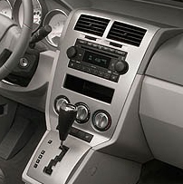
2008 Dodge Caliber Audio Wiring Radio Diagram Schematic Colors – Aftermarket Installation Help

Car Radio Constant 12v+ Wire: Red/Light Blue
Car Stereo Ground Wire: Black/Yellow or Black/Green
Car Radio Ignition Switched Wire: @ Cigarette Lighter Below Radio
Car Radio Illumination Wire: White/Purple @ Drivers kick panel harness
Car Stereo Power Antenna: Gray/Red (+) @ Radio Harness
Car Radio Amp Turn On Wire:

Left Front Speaker Wire (+) Positive: Gray/Purple
Left Front Speaker Wire (-) Negative: Gray/Yellow
Right Front Speaker Wire (+) Positive: Green/Purple
Right Front Speaker Wire (-) Negative: Green/Yellow

Left Rear Speaker Wire (+) Positive: Green/Dark Blue
Left Rear Speaker Wire (-) Negative: Green/Brown
Right Rear Speaker Wire (+) Positive: Gray/Dark Blue
Right Rear Speaker Wire (-) Negative: Gray/Orange

SPEAKER WIRE COLORS AT THE SPEAKERS IN THE DOORS

Left Front Door Speaker Wire (+) Positive:
Left Front Door Speaker Wire (-) Negative:

Right Front Door Speaker Wire (+) Positive:
Right Front Door Speaker Wire (-) Negative:

Left Rear Door Speaker Wire (+) Positive:
Left Rear Door Speaker Wire (-) Negative:

Right Rear Door Speaker Wire (+) Positive:
Right Rear Door Speaker Wire (-) Negative:

Center Channel Speaker Wire Positive / Negative: N/A

Subwoofer Speaker Wire Positive / Negative: N/A

Radio Size: Single or Double Din

Radio Removal Tools:

Keep in mind if you are installing a new radio you need the wiring harness, the antenna adapter, steering wheel control module, and the mounting kit as well.

REQUIRED PARTS FOR AFTERMARKET RADIO INSTALL

AMPLIFIED SYSTEM WIRING HARNESS:

BASE SYSTEM WIRING HARNESS:

MOUNTING KIT FOR DOUBLE DIN AFTERMARKET RADIOS:

(This kit can be used with double or single din radios! Vehicle MUST have OEM navigation to use this kit OR you will also need to purchase the OEM Nav Bezel
.

MOUNTING KIT FOR SINGLE DIN AFTERMARKET RADIOS:

(This kit can be used ONLY with single din radios! Vehicle must NOT have OEM navigation.

ANTENNA ADAPTER:

STEERING WHEEL CONTROLS ADAPTER:

Metra Axxess ASWC-1 Universal Steering Wheel Control Interface

SPEAKER WIRING ADAPTERS:

Use these when replacing the OEM speakers if you don’t want to cut or splice the OEM harness. Comes with 1 pair if doing all 4 speakers you will need to order 2.

RECOMMENDED TOOLS FOR THE INSTALL – SAME ONES THE PROS USE!

– 3M Electrical Tape

– Install Bay Butt Connectors

– Klein Wire Cutters / Crimpers

– Gardner Bender Auto Wire Stripper

– Dash Removal Plastic Pry Tools

2007 Dodge Caliber Radio Audio Wiring Diagram Schematic Colors

Here is the stereo radio wiring information for your 2007 Dodge Caliber body with the standard or amplified systems. It will be useful when installing an aftermarket radio, sound stereo system, or other automotive accessories. Make sure to grab the appropriate tools to test all the wires in your Caliber. Please check it over and use it as a GUIDE to help you locate the appropriate wires. This schematic is provided free of charge and may not be 100% accurate. Failure to properly test all the wires may lead to vehicle or bodily damage. All information is provided as-is and accuracy is not guaranteed.

Dodge Caliber Audio Radio Wiring Diagram Schematic

If you find any conflicting info please leave a comment with what you found in your Dodge Caliber. If you don’t see the audio radio wiring diagram you need comment and we will try to add it ASAP. Thanks for looking!

2007 Dodge Caliber Audio Wiring Radio Diagram Schematic Colors

Car Radio Constant 12v+ Wire: Red/Light Blue
Car Stereo Ground Wire: Black/Yellow or Black/Green
Car Radio Ignition Switched Wire: @ Cigarette Lighter Below Radio
Car Radio Illumination Wire: White/Purple @ Drivers kick panel harness
Car Stereo Power Antenna: Gray/Red (+) @ Radio Harness
Car Radio Amp Turn On Wire:

Left Front Speaker Wire (+) Positive: Gray/Purple
Left Front Speaker Wire (-) Negative: Gray/Yellow
Right Front Speaker Wire (+) Positive: Green/Purple
Right Front Speaker Wire (-) Negative: Green/Yellow

Left Rear Speaker Wire (+) Positive: Green/Dark Blue
Left Rear Speaker Wire (-) Negative: Green/Brown
Right Rear Speaker Wire (+) Positive: Gray/Dark Blue
Right Rear Speaker Wire (-) Negative: Gray/Orange

SPEAKER WIRE COLORS AT THE SPEAKERS IN THE DOORS

Left Front Door Speaker Wire (+) Positive:
Left Front Door Speaker Wire (-) Negative:
Right Front Door Speaker Wire (+) Positive:
Right Front Door Speaker Wire (-) Negative:

Left Rear Door Speaker Wire (+) Positive:
Left Rear Door Speaker Wire (-) Negative:
Right Rear Door Speaker Wire (+) Positive:
Right Rear Door Speaker Wire (-) Negative:

Center Channel Speaker Wire Positive / Negative: N/A

Subwoofer Speaker Wire Positive / Negative: N/A

Radio Size: Single or Double Din

Radio Removal Tools:

Keep in mind if you are installing a new radio you need the wiring harness, the antenna adapter, steering wheel control module, and the mounting kit as well.

REQUIRED PARTS FOR AFTERMARKET RADIO INSTALL

BASE SYSTEM WIRING HARNESS:

AMPLIFIED SYSTEM WIRING HARNESS:

MOUNTING KIT FOR DOUBLE DIN AFTERMARKET RADIOS:

(This kit can be used with double or single din radios! Vehicle MUST have OEM navigation to use this kit OR you will also need to purchase the OEM Nav Bezel
.

MOUNTING KIT FOR SINGLE DIN AFTERMARKET RADIOS:

(This kit can be used ONLY with single din radios! Vehicle must NOT have OEM navigation.

ANTENNA ADAPTER:

STEERING WHEEL CONTROLS ADAPTER:

Metra Axxess ASWC-1 Universal Steering Wheel Control Interface

SPEAKER WIRING ADAPTERS:

Use these when replacing the OEM speakers if you don’t want to cut or splice the OEM harness. Comes with 1 pair if doing all 4 speakers you will need to order 2.

RECOMMENDED TOOLS FOR THE INSTALL – SAME ONES THE PROS USE!

– 3M Electrical Tape

– Install Bay Butt Connectors

– Klein Wire Cutters / Crimpers

– Gardner Bender Auto Wire Stripper

– Dash Removal Plastic Pry Tools

2002 Mercedes Benz MB W203 C230 Kompressor Radio Audio Wiring Diagram Schematic Colors

Here is the stereo radio wiring information for your 2002 MB C230 W203 Kompressor body with the standard or amplified systems. It will be useful when installing an aftermarket radio, sound stereo system, or other automotive accessories. Make sure to grab the appropriate tools to test all the wires in your C230. Please check it over and use it as a GUIDE to help you locate the appropriate wires. This schematic is provided free of charge and may not be 100% accurate. Failure to properly test all the wires may lead to vehicle or bodily damage. All information is provided as-is and accuracy is not guaranteed.

2002 Mercedes W203 C230 Audio Wiring Diagram

If you find any conflicting info please leave a comment with what you found in your W203 C230. If you don’t see the audio radio wiring diagram you need comment and we will try to add it ASAP. Thanks for looking!

2002 MB W203 C230 Kompressor Audio Wiring Radio Diagram Schematic Colors

Car Radio Constant 12v+ Wire: Red/Blue
Car Stereo Ground Wire: Brown
Car Radio Ignition Switched Wire: Black/Yellow @ Cigarette Lighter Below Radio
Car Radio Illumination Wire: Gray/Blue @ Cigarette Lighter Below Radio
Car Stereo Power Antenna: Black (+) @ Radio Harness
Car Radio Amp Turn On Wire:

Left Front Speaker Wire (+) Positive: Light Green
Left Front Speaker Wire (-) Negative: Brown/Light Green
Right Front Speaker Wire (+) Positive: Orange
Right Front Speaker Wire (-) Negative: Brown/Orange

Left Rear Speaker Wire (+) Positive: Pink
Left Rear Speaker Wire (-) Negative: Brown/Pink
Right Rear Speaker Wire (+) Positive: White
Right Rear Speaker Wire (-) Negative: Brown/White

SPEAKER WIRE COLORS AT THE SPEAKERS IN THE DOORS

Left Front Door Speaker Wire (+) Positive:
Left Front Door Speaker Wire (-) Negative:
Right Front Door Speaker Wire (+) Positive:
Right Front Door Speaker Wire (-) Negative:

Left Rear Door Speaker Wire (+) Positive:
Left Rear Door Speaker Wire (-) Negative:
Right Rear Door Speaker Wire (+) Positive:
Right Rear Door Speaker Wire (-) Negative:

Center Channel Speaker Wire Positive / Negative: N/A

Subwoofer Speaker Wire Positive / Negative: N/A

Radio Size: Single or Double Din

Radio Removal Tools: Plastic Bezel Removal Tools to pop the shifter gear selector trim (don’t completely remove). Then pop the larger shifter bezel and remove that over the smaller one. Use the pick tools to remove the pocket and cigarette lighter bezel. Next use the pick tools to release the spring clips inside the vents and rotate the vents upward to reveal torx screws to remove using this Torx Driver Set. Return the vents to their normal position then use the pick tools to release the spring clips and rotate the vents downward to reveal clips up top to pull down a bit to remove the vent panel. After that remove the torx at the top of radio bezel, and the metal clips at the bottom then unplug and remove that bezel. (don’t turn the vehicle on once you unplug the airbag connector). Finally 4 screws hold the radio in.

Keep in mind if you are installing a new radio you need the wiring harness, the antenna adapter, steering wheel control module, and the mounting kit as well.

REQUIRED PARTS FOR AFTERMARKET RADIO INSTALL

BASE SYSTEM WIRING HARNESS:

MOUNTING KIT FOR DOUBLE DIN AFTERMARKET RADIOS:

(This kit can be used with double din radios only!)

MOUNTING KIT FOR SINGLE DIN AFTERMARKET RADIOS:

(This kit can be used with single din radios!)

ANTENNA ADAPTER:

STEERING WHEEL CONTROLS ADAPTER:

Metra Axxess ASWC-1 Universal Steering Wheel Control Interface

RECOMMENDED TOOLS FOR THE INSTALL – SAME ONES THE PROS USE!

– 3M Electrical Tape

– Install Bay Butt Connectors

– Klein Wire Cutters / Crimpers

– Gardner Bender Auto Wire Stripper

– Dash Removal Plastic Pry Tools

2012 VW MK6 Jetta Radio Audio Wiring Diagram Schematic Colors

Here is the stereo radio wiring information for your 2012 Volkswagen Jetta MK6 body with the standard or amplified systems. It will be useful when installing an aftermarket radio, sound stereo system, or other automotive accessories. Make sure to grab the appropriate tools to test all the wires in your Jetta. Please check it over and use it as a GUIDE to help you locate the appropriate wires. This schematic is provided free of charge and may not be 100% accurate. Failure to properly test all the wires may lead to vehicle or bodily damage. All information is provided as-is and accuracy is not guaranteed.

2012 VW Jetta Audio Wiring Diagram Radio Install
2012 VW Jetta Audio Wiring Diagram

If you find any conflicting info please leave a comment with what you found in your MK6 VW Jetta. If you don’t see the audio radio wiring diagram you need comment and we will try to add it ASAP. Thanks for looking!

2012 VW Jetta Audio Wiring Radio Diagram Schematic Colors

Car Radio Constant 12v+ Wire: Red/Yellow
Car Stereo Ground Wire: Brown
Car Radio Ignition Switched Wire: Not at Radio – Use the adapter found below OR connect at the driver underdash fusebox:

Car Stereo VSS Speed Wire: Data see below
Car Stereo Reverse Wire + : Data see below
Car Stereo Dimmer Wire: Data see below
Car Radio Illumination Wire: Connect at lighted cigarette lighter
Car Stereo Power Antenna: Built Into Antenna Adapter (See Below)
Car Radio Amp Turn On Wire: N/A

Left Front Speaker Wire (+) Positive: Brown/Green
Left Front Speaker Wire (-) Negative: Brown/Blue
Right Front Speaker Wire (+) Positive: Brown/Red
Right Front Speaker Wire (-) Negative: Brown/Black

Left Rear Speaker Wire (+) Positive: Red/White
Left Rear Speaker Wire (-) Negative: Brown/White
Right Rear Speaker Wire (+) Positive: Red/Purple
Right Rear Speaker Wire (-) Negative: Brown/Purple

SPEAKER WIRE COLORS AT THE SPEAKERS IN THE DOORS

Left Front Door Speaker Wire (+) Positive: Red/Blue
Left Front Door Speaker Wire (-) Negative: Brown/Blue
Right Front Door Speaker Wire (+) Positive: Red/Blue
Right Front Door Speaker Wire (-) Negative: Brown/Blue

Left Rear Door Speaker Wire (+) Positive: White/Gray
Left Rear Door Speaker Wire (-) Negative: Blue/Gray
Right Rear Door Speaker Wire (+) Positive: White/Gray
Right Rear Door Speaker Wire (-) Negative: Blue/Gray

Center Channel Speaker Wire Positive / Negative: N/A

Subwoofer Speaker Wire Positive / Negative: N/A

Radio Size: Single or Double Din

Radio Removal: Using plastic bezel removal tools carefully pop the radio bezel from the dash. Take note of the airbag light at the bottom of the bezel. If you unplug that with the key turned on, or turn the key on after unplugging it – you will set an airbag light that will NOT go away without a trip to the dealer. Unplug all the connectors and remove the dash bezel. The radio is then held in with 4 screws.

Keep in mind if you are installing a new radio you need the wiring harness, the antenna adapter, steering wheel control module, and the mounting kit as well.

REQUIRED PARTS FOR AFTERMARKET RADIO INSTALL

BASE SYSTEM WIRING HARNESS – ECONOMY INSTALL:

This harness will work great to install an aftermarket radio, but you will need to run your own ignition turn on lead to the fusebox and connect using the fuse tap below.

ADVANCED HARNESS:

This harness will provide a turn on lead as well as illumination, reverse, and vehicle speed outputs. Worth the extra money if you are installing a navigation radio or adding a backup camera.

Axxess XSVI-9003-NAV

MOUNTING KIT FOR DOUBLE DIN AFTERMARKET RADIOS:

(This kit can be used with double din radios only – has a nice matte finish to match the OEM look!)

MOUNTING KIT FOR SINGLE DIN AFTERMARKET RADIOS:

(This kit can be used with single or double din radios – has a nice matte finish to match the OEM look!)

ANTENNA ADAPTER:

Depending on radio these vehicles may have the single OR dual Fakra antenna. You will need 1 of the antenna adapters below unfortunately the only way to know for sure is to pull the radio and see what your antenna lead looks like:

SPEAKER ADAPTERS FOR INSTALL:

Use these to install aftermarket speakers for ideal positioning in the door. If doing front and rear doors you would need 2 pairs.

STEERING WHEEL CONTROLS ADAPTER:

Metra Axxess ASWC-1 Universal Steering Wheel Control Interface

RECOMMENDED TOOLS FOR THE INSTALL – SAME ONES THE PROS USE!

– 3M Electrical Tape

– Install Bay Butt Connectors

– Klein Wire Cutters / Crimpers

– Gardner Bender Auto Wire Stripper

– Dash Removal Plastic Pry Tools

1988 BMW 325ix E30 Radio Audio Wiring Diagram Schematic Colors

Here is the stereo radio wiring information for your 1988 BMW 325ix E30 with the standard or amplified systems. It will be useful when installing an aftermarket radio, sound stereo system, or other automotive accessories. Make sure to grab the appropriate tools to test all the wires in your 325i E30. Please check it over and use it as a GUIDE to help you locate the appropriate wires. This schematic is provided free of charge and may not be 100% accurate. Failure to properly test all the wires may lead to vehicle or bodily damage. All information is provided as-is and accuracy is not guaranteed.

1988 BMW 325ix E30 radio stereo wiring diagram

If you find any conflicting info please leave a comment with what you found in your 1988 BMW 325ix E30. If you don’t see the audio radio wiring diagram you need comment and we will try to add it ASAP. Thanks for looking!

(MAKE SURE TO SCROLL TO THE BOTTOM TO SEE IF ANY OTHER READERS POSTED ANY OTHER TIPS AND TRICKS!)

1988 BMW 325ix E30 Audio Wiring Radio Diagram Schematic Colors

Car Radio Constant 12v+ Wire: Red/Green – @ Stereo Harness
Car Stereo Ground Wire: Brown or Brown/Black – @ Stereo Harness
Car Radio Ignition Switched Wire: Purple/White or Purple/Gray – @ Stereo Harness
Car Stereo VSS Speed Wire: N/A
Car Stereo Reverse Backup Wire + : N/A
Car Stereo Dimmer Wire: N/A
Car Radio Illumination Wire: Gray/Red (+) @ Stereo Harness
Car Stereo Power Antenna: White (+) @ Radio Harness
Car Radio Amp Turn On Wire: White (+) @ Radio Harness – Same wire as above.

WITHOUT OEM AMP: SPEAKER WIRE COLORS AT THE SPEAKERS OR AT THE FADER SWITCH ABOVE THE RADIO – MUST CUT AND CONNECT

Left Front Speaker Wire (+) Positive: Yellow/Red
Left Front Speaker Wire (-) Negative: Yellow/Brown
Right Front Speaker Wire (+) Positive: Blue/Red
Right Front Speaker Wire (-) Negative: Blue/Brown
Left Rear Speaker Wire (+) Positive: Yellow/Black
Left Rear Speaker Wire (-) Negative: Yellow/Brown
Right Rear Speaker Wire (+) Positive: Blue/Black
Right Rear Speaker Wire (-) Negative: Blue/Brown
Center Channel Speaker Wire Positive / Negative: N/A
Subwoofer Speaker Wire Positive / Negative: N/A

WITH OEM AMP: SPEAKER WIRE COLORS AT THE SPEAKERS OR AT THE AMP DRIVER SIDE TRUNK AREA

Left Front Speaker Wire (+) Positive: Gray/Red
Left Front Speaker Wire (-) Negative: Gray/Purple
Right Front Speaker Wire (+) Positive: Gray/White
Right Front Speaker Wire (-) Negative: Gray/Brown
Left Rear Speaker Wire (+) Positive: Black/Red
Left Rear Speaker Wire (-) Negative: Black/Purple
Right Rear Speaker Wire (+) Positive: Gray/Red
Right Rear Speaker Wire (-) Negative: Gray/Purple
Center Channel Speaker Wire Positive / Negative: N/A
Subwoofer Speaker Wire Positive / Negative: N/A

Radio Size: Single Din

Speaker Size Front: N/A
Speaker Size Rear: N/A
Speaker Size Subwoofer: N/A

When installing a new radio you won’t need a mounting kit or antenna adapter for this vehicle, but you will need the BMW Radio Removal Tool

REQUIRED PARTS FOR AFTERMARKET RADIO INSTALL

RECOMMENDED TOOLS FOR THE INSTALL – SAME ONES THE PROS USE!

– 3M Electrical Tape

– Install Bay Butt Connectors

– Dash Removal Plastic Pry Tools

– Gardner Bender Auto Wire Stripper

– Klein Wire Cutters / Crimpers

2013 Kia Sorento Radio Audio Wiring Diagram Schematic Colors

Here is the stereo radio wiring information for your 2013 Kia Sorento with the standard or UVO amplified systems. It will be useful when installing an aftermarket radio, sound stereo system, or other automotive accessories. Make sure to grab the appropriate tools to test all the wires in your Sorento. Please check it over and use it as a GUIDE to help you locate the appropriate wires. This schematic is provided free of charge and may not be 100% accurate. Failure to properly test all the wires may lead to vehicle or bodily damage. All information is provided as-is and accuracy is not guaranteed.

2013 Kia Sorento Radio Audio Wiring Diagram

If you find any conflicting info please leave a comment with what you found in your 2013 Kia Sorento. If you don’t see the audio radio wiring diagram you need comment and we will try to add it ASAP. Thanks for looking!

(MAKE SURE TO SCROLL TO THE BOTTOM TO SEE IF ANY OTHER READERS POSTED ANY OTHER TIPS AND TRICKS!)

2013 Kia Sorento Audio Wiring Radio Diagram Schematic Colors

Car Radio Constant 12v+ Wire: Red/Orange – Gray Plug Pin 4 or White Plug Pin 12
Car Stereo Ground Wire: Black – Gray Plug Pin 8 or White Plug Pin 24
Car Radio Ignition Switched Wire: White/Orange or Blue/Orange – Gray Plug Pin 6 or White Plug Pin 11
Car Stereo VSS Speed Wire: Brown – Gray Plug Pin 1 or White Plug Pin 16
Car Stereo Reverse Backup Wire + : Red (+) @ Light or Dash Fusebox White Plug Pin 15
Car Stereo Dimmer Wire: Black/Orange – Gray Plug Pin 7 or Smaller White Plug Pin 17
Car Radio Illumination Wire: Yellow – Gray Plug Pin 2 or Smaller White Plug Pin 8
Car Stereo Power Antenna: Green (+) Gray Plug Pin 3 or Smaller White Plug Pin 18
Car Radio Amp Turn On Wire: N/A – CAN DATA

Left Front Speaker Wire (+) Positive: Brown – Brown Plug Pin 3
Left Front Speaker Wire (-) Negative: White – Brown Plug Pin 7
Right Front Speaker Wire (+) Positive: Blue – Brown Plug Pin 2
Right Front Speaker Wire (-) Negative: Red – Brown Plug Pin 6

Left Rear Speaker Wire (+) Positive: Yellow – Brown Plug Pin 4
Left Rear Speaker Wire (-) Negative: Black – Brown Plug Pin 8
Right Rear Speaker Wire (+) Positive: Green – Brown Plug Pin 1
Right Rear Speaker Wire (-) Negative: Orange – Brown Plug Pin 5
Center Channel Speaker Wire Positive / Negative: Blue (+) / Red (-) (with amp only) Under passenger seat. Gray plug pins 7 / 15

Subwoofer Speaker Wire Positive / Negative: Green / Orange – Under passenger seat. Gray plug pins 13 / 26 & Blue / Red – Gray plug pins 12 / 25

Want to keep your OEM aux AND USB jack to work with your new aftermarket radio. You need this:

Axxess Retains OE USB Port On Select Hyundai/Kia Vehicles

Radio Size: Single or Double Din

Speaker Size Front: 6.5″
Speaker Size Rear: 6.5″
Speaker Size Subwoofer: N/A

Keep in mind if you are installing a new radio you need the mounting kit, the wiring harness, the antenna adapter, and the steering wheel control adapter if you have audio controls on the wheel you want to keep.

REQUIRED PARTS FOR AFTERMARKET RADIO INSTALL

WIRING HARNESS:

MOUNTING KIT FOR DOUBLE DIN AFTERMARKET RADIOS:

MOUNTING KIT FOR SINGLE DIN AFTERMARKET RADIOS:

ANTENNA ADAPTER FOR INSTALL:

SPEAKER WIRING ADAPTER FOR INSTALL:

N/A

STEERING WHEEL CONTROLS ADAPTER:

Metra Axxess ASWC-1 Universal Steering Wheel Control Interface

RECOMMENDED TOOLS FOR THE INSTALL – SAME ONES THE PROS USE!

– 3M Electrical Tape

– Install Bay Butt Connectors

– Dash Removal Plastic Pry Tools

– Gardner Bender Auto Wire Stripper

– Klein Wire Cutters / Crimpers

2013 Chrysler 200 Radio Audio Wiring Diagram Schematic Colors

Here is the stereo radio wiring information for your 2013 Chrysler 200 with the standard or amplified systems. It will be useful when installing an aftermarket radio, sound stereo system, or other automotive accessories. Make sure to grab the appropriate tools to test all the wires in your 200. Please check it over and use it as a GUIDE to help you locate the appropriate wires. This schematic is provided free of charge and may not be 100% accurate. Failure to properly test all the wires may lead to vehicle or bodily damage. All information is provided as-is and accuracy is not guaranteed.

2013 Chrysler 200 Audio Radio Wiring Diagram

If you find any conflicting info please leave a comment with what you found in your 2013 Chrysler 200. If you don’t see the audio radio wiring diagram you need comment and we will try to add it ASAP. Thanks for looking!

(MAKE SURE TO SCROLL TO THE BOTTOM TO SEE IF ANY OTHER READERS POSTED ANY OTHER TIPS AND TRICKS!)

2013 Chrysler 200 Audio Wiring Radio Diagram Schematic Colors

Car Radio Constant 12v+ Wire: Red/Brown @ Pin 1
Car Stereo Ground Wire: Black – Pin 12
Car Radio Ignition Switched Wire: @ Cigarette Lighter or Interface

Car Stereo VSS Speed Wire: N/A
Car Stereo Reverse Wire + : White/Green (+) @ Light
Car Stereo Dimmer Wire: N/A
Car Radio Illumination Wire: White/Purple (Parking Lights) @ Driver kick
Car Stereo Power Antenna: Gray/Orange (+) @ Pin 7
Car Radio Amp Turn On Wire: N/A

Left Front Speaker Wire (+) Positive: Gray/Purple – Pin 21
Left Front Speaker Wire (-) Negative: Gray/Yellow – Pin 22
Right Front Speaker Wire (+) Positive: Dark Green/Purple – Pin 19
Right Front Speaker Wire (-) Negative: Dark Green/Yellow – Pin 20

Left Rear Speaker Wire (+) Positive: Dark Green/Tan – Pin 8
Left Rear Speaker Wire (-) Negative: Dark Green/Gray – Pin 9
Right Rear Speaker Wire (+) Positive: Dark Green/Brown – Pin 10
Right Rear Speaker Wire (-) Negative: Yellow/Gray – Pin 11

Center Channel Speaker Wire Positive / Negative: N/A

Subwoofer Speaker Wire Positive / Negative: N/A

Radio Size: Single or Double Din

Speaker Size Front: 6×9″
Speaker Size Rear: 6×9″
Speaker Size Subwoofer: N/A

Use the adapters below to install common 6.5″ speakers in the doors.

Check out these Infinity Kappa 6 x 9’s
they work great and are an excellent bang for the buck if you want to replace and upgrade your door speakers.

Radio Removal: Using plastic bezel removal tools carefully pop the radio bezel from the dash. Unplug all the connectors and remove the dash bezel. The radio and pocket below is then held in with 4 torx screws.

Keep in mind if you are installing a new radio you need the mounting kit, the wiring harness, the antenna adapter, and the steering wheel control adapter if you have audio controls on the wheel you want to keep.

REQUIRED PARTS FOR AFTERMARKET RADIO INSTALL

BASIC ECONOMY WIRING HARNESS WITHOUT OEM AMPLIFIED SYSTEM:

You will need to run the switched turn on from your radio to a ignition source but this harness will work great otherwise. See the other options below to save some time on the install!

ADVANCED WIRING HARNESS WITHOUT OEM AMPLIFIED SYSTEM:

Will provide switch turn on ignition lead, illumination and nav outputs like park brake, speed VSS, backup reverse wire, etc.

WIRING HARNESS WITH OEM AMPLIFIED SYSTEM:

Will also provide switch ignition power and nav outputs like parking brake, VSS speed, reverse wire, etc.

ANTENNA ADAPTER FOR INSTALL:

MOUNTING KIT FOR DOUBLE DIN AFTERMARKET RADIOS:

MOUNTING KIT FOR SINGLE DIN AFTERMARKET RADIOS:

CUSTOM UNDER SEAT BOX ENCLOSURE FOR ADDING AFTERMARKET SUB WOOFER:

Not available use a basic box like seen below to save on space and get plenty of bass!

SPEAKER WIRING ADAPTER FOR INSTALL:

Use these if you don’t want to tap in or cut off your existing speaker connectors. They plug right in then right on to the new speaker making installation a breeze. Order quantity 2 if doing front and rear speakers.

STEERING WHEEL CONTROLS ADAPTER:

Use this to retain the use of your OEM audio steering wheel controls with your new aftermarket radio. Works great easy wiring and simple programming.

Metra Axxess ASWC-1 Universal Steering Wheel Control Interface

RECOMMENDED TOOLS FOR THE INSTALL – SAME ONES THE PROS USE!

– Gardner Bender Auto Wire Stripper

– Klein Wire Cutters / Crimpers

– 3M Electrical Tape

– Dash Removal Plastic Pry Tools

– Install Bay Butt Connectors

2014 Chrysler 200 Audio Radio Wiring Diagram Schematic Colors

Here is the stereo radio wiring information for your 2014 Chrysler 200 with the standard or amplified systems. It will be useful when installing an aftermarket radio, sound stereo system, or other automotive accessories. Make sure to grab the appropriate tools to test all the wires in your 200. Please check it over and use it as a GUIDE to help you locate the appropriate wires. This schematic is provided free of charge and may not be 100% accurate. Failure to properly test all the wires may lead to vehicle or bodily damage. All information is provided as-is and accuracy is not guaranteed.

2014 Chrysler 200 Audio Radio Wiring Diagram

If you find any conflicting info please leave a comment with what you found in your 2014 Chrysler 200. If you don’t see the audio radio wiring diagram you need comment and we will try to add it ASAP. Thanks for looking!

(MAKE SURE TO SCROLL TO THE BOTTOM TO SEE IF ANY OTHER READERS POSTED ANY OTHER TIPS AND TRICKS!)

2014 Chrysler 200 Audio Wiring Radio Diagram Schematic Colors

Car Radio Constant 12v+ Wire: Red/Brown @ Pin 1
Car Stereo Ground Wire: Black – Pin 12
Car Radio Ignition Switched Wire: @ Cigarette Lighter or Interface

Car Stereo VSS Speed Wire: N/A
Car Stereo Reverse Wire + : White/Green (+) @ Light
Car Stereo Dimmer Wire: N/A
Car Radio Illumination Wire: White/Purple (Parking Lights) @ Driver kick
Car Stereo Power Antenna: Gray/Orange (+) @ Pin 7
Car Radio Amp Turn On Wire: N/A

Left Front Speaker Wire (+) Positive: Gray/Purple – Pin 21
Left Front Speaker Wire (-) Negative: Gray/Yellow – Pin 22
Right Front Speaker Wire (+) Positive: Dark Green/Purple – Pin 19
Right Front Speaker Wire (-) Negative: Dark Green/Yellow – Pin 20

Left Rear Speaker Wire (+) Positive: Dark Green/Tan – Pin 8
Left Rear Speaker Wire (-) Negative: Dark Green/Gray – Pin 9
Right Rear Speaker Wire (+) Positive: Dark Green/Brown – Pin 10
Right Rear Speaker Wire (-) Negative: Yellow/Gray – Pin 11

Center Channel Speaker Wire Positive / Negative: N/A

Subwoofer Speaker Wire Positive / Negative: N/A

Radio Size: Single or Double Din

Speaker Size Front: 6×9″
Speaker Size Rear: 6×9″
Speaker Size Subwoofer: N/A

Use the adapters below to install common 6.5″ speakers in the doors.

Check out these Infinity Kappa 6 x 9’s
they work great and are an excellent bang for the buck if you want to replace and upgrade your door speakers.

Radio Removal: Using plastic bezel removal tools carefully pop the radio bezel from the dash. Unplug all the connectors and remove the dash bezel. The radio and pocket below is then held in with 4 torx screws.

Keep in mind if you are installing a new radio you need the mounting kit, the wiring harness, the antenna adapter, and the steering wheel control adapter if you have audio controls on the wheel you want to keep.

REQUIRED PARTS FOR AFTERMARKET RADIO INSTALL

BASIC ECONOMY WIRING HARNESS WITHOUT OEM AMPLIFIED SYSTEM:

You will need to run the switched turn on from your radio to a ignition source but this harness will work great otherwise. See the other options below to save some time on the install!

ADVANCED WIRING HARNESS WITHOUT OEM AMPLIFIED SYSTEM:

Will provide switch turn on ignition lead, illumination and nav outputs like park brake, speed VSS, backup reverse wire, etc.

WIRING HARNESS WITH OEM AMPLIFIED SYSTEM:

Will also provide switch ignition power and nav outputs like parking brake, VSS speed, reverse wire, etc.

ANTENNA ADAPTER FOR INSTALL:

MOUNTING KIT FOR DOUBLE DIN AFTERMARKET RADIOS:

MOUNTING KIT FOR SINGLE DIN AFTERMARKET RADIOS:

CUSTOM UNDER SEAT BOX ENCLOSURE FOR ADDING AFTERMARKET SUB WOOFER:

Not available use a basic box like seen below to save on space and get plenty of bass!

SPEAKER WIRING ADAPTER FOR INSTALL:

Use these if you don’t want to tap in or cut off your existing speaker connectors. They plug right in then right on to the new speaker making installation a breeze. Order quantity 2 if doing front and rear speakers.

STEERING WHEEL CONTROLS ADAPTER:

Use this to retain the use of your OEM audio steering wheel controls with your new aftermarket radio. Works great easy wiring and simple programming.

Metra Axxess ASWC-1 Universal Steering Wheel Control Interface

RECOMMENDED TOOLS FOR THE INSTALL – SAME ONES THE PROS USE!

– Gardner Bender Auto Wire Stripper

– Klein Wire Cutters / Crimpers

– 3M Electrical Tape

– Install Bay Butt Connectors

– Dash Removal Plastic Pry Tools

2006 Honda Ridgeline Audio Radio Wiring Diagram Schematic Colors

Here is the stereo radio wiring information for your 2006 Honda Ridgeline with the standard or amplified systems. It will be useful when installing an aftermarket radio, sound stereo system, or other automotive accessories. Make sure to grab the appropriate tools to test all the wires in your Ridgeline. Please check it over and use it as a GUIDE to help you locate the appropriate wires. This schematic is provided free of charge and may not be 100% accurate. Failure to properly test all the wires may lead to vehicle or bodily damage. All information is provided as-is and accuracy is not guaranteed.

2006 Honda Ridgeline Audio Wiring Radio

If you find any conflicting info please leave a comment with what you found in your 2006 Honda Ridgeline. If you don’t see the audio radio wiring diagram you need comment and we will try to add it ASAP. Thanks for looking!

(MAKE SURE TO SCROLL TO THE BOTTOM TO SEE IF ANY OTHER READERS POSTED ANY OTHER TIPS AND TRICKS!)

2006 Honda Ridgeline Audio Wiring Radio Diagram Schematic Colors

Car Radio Constant 12v+ Wire: White – Pin 10
Car Stereo Ground Wire: Black – Pin 20
Car Radio Ignition Switched Wire: Yellow/Red Pin 2 @ Radio Harness

Car Stereo VSS Speed Wire: N/A
Car Stereo Reverse Wire + : Green (+) @ Light
Car Stereo Dimmer Wire: Red @ Pin 19
Car Radio Illumination Wire: Red/Black (Parking Lights) @ Pin 9
Car Stereo Power Antenna: Black (+) Pin 3 @ Antenna Plug
Car Radio Amp Turn On Wire: N/A

Left Front Speaker Wire (+) Positive: Light Green – Pin 8
Left Front Speaker Wire (-) Negative: Violet – Pin 18
Right Front Speaker Wire (+) Positive: Blue – Pin 7
Right Front Speaker Wire (-) Negative: Red – Pin 17

Left Rear Speaker Wire (+) Positive: Brown/White – Pin 6
Left Rear Speaker Wire (-) Negative: Red/Yellow – Pin 16
Right Rear Speaker Wire (+) Positive: Red/Blue – Pin 5
Right Rear Speaker Wire (-) Negative: Yellow – Pin 15

Center Channel Speaker Wire Positive / Negative: N/A

Subwoofer Speaker Wire Positive / Negative: Yellow/Black & Light Green/Red

These wires let you keep your OEM aux jack to work with your new aftermarket radio. Grab a cheap RCA Auxiliary Cable plug either the aux or the rcas into the back of your new aftermarket radio depending on what type of audio input they have. Then cut off the other end and splice into the following wires at the 14-pin connector found behind the radio:

OEM AUX Audio Left Signal: White @ 6 pin connector pin 5
OEM AUX Audio Left Ground: Red @ 6 pin connector pin 4
OEM AUX Audio Right Signal: Brown @ 6 pin connector pin 3
OEM AUX Audio Right Ground Red @ 6 pin connector pin 4

Radio Size: Single or Double Din

Speaker Size Front: 6.5″
Speaker Size Rear: 6.5″
Speaker Size Subwoofer: 8″

Use the adapters below to install common 6.5″ speakers in the doors. Depending on the size and depth of speakers you still may need to cut some of the door metal away. Use some tin snips to easily get the job done.

Check out these Infinity Reference 6.5-Inch speakers they work great and are an excellent bang for the buck! Or the component version if you want to replace your OEM tweeters in the dash as well.

Radio Removal: Using plastic bezel removal tools carefully pop the radio bezel from the dash. Unplug all the connectors and remove the dash bezel. The radio and pocket below is then held in with 5 screws.

Keep in mind if you are installing a new radio you need the mounting kit, the wiring harness, the antenna adapter, and the steering wheel control adapter if you have audio controls on the wheel you want to keep.

REQUIRED PARTS FOR AFTERMARKET RADIO INSTALL

WIRING HARNESS:

ANTENNA ADAPTER FOR INSTALL:

GRAY MOUNTING KIT FOR DOUBLE DIN AFTERMARKET RADIOS:

TAN MOUNTING KIT FOR DOUBLE DIN AFTERMARKET RADIOS:

GRAY MOUNTING KIT FOR SINGLE DIN AFTERMARKET RADIOS:

TAN MOUNTING KIT FOR SINGLE DIN AFTERMARKET RADIOS:

CUSTOM UNDER SEAT BOX ENCLOSURE FOR ADDING AFTERMARKET SUB WOOFER:

SPEAKER WIRING ADAPTER FOR INSTALL:

Use these if you don’t want to tap in or cut off your existing speaker connectors. They plug right in then right on to the new speaker making installation a breeze. Order quantity 2 if doing front and rear speakers.

STEERING WHEEL CONTROLS ADAPTER:

Metra Axxess ASWC-1 Universal Steering Wheel Control Interface

RECOMMENDED TOOLS FOR THE INSTALL – SAME ONES THE PROS USE!

– Gardner Bender Auto Wire Stripper

– Klein Wire Cutters / Crimpers

– 3M Electrical Tape

– Install Bay Butt Connectors

– Dash Removal Plastic Pry Tools

2007 Honda Ridgeline Audio Radio Wiring Diagram Schematic Colors

Here is the stereo radio wiring information for your 2007 Honda Ridgeline with the standard or amplified systems. It will be useful when installing an aftermarket radio, sound stereo system, or other automotive accessories. Make sure to grab the appropriate tools to test all the wires in your Ridgeline. Please check it over and use it as a GUIDE to help you locate the appropriate wires. This schematic is provided free of charge and may not be 100% accurate. Failure to properly test all the wires may lead to vehicle or bodily damage. All information is provided as-is and accuracy is not guaranteed.

2007 Honda RIdgeline Audio Radio Wiring DIagram

If you find any conflicting info please leave a comment with what you found in your 2007 Honda Ridgeline. If you don’t see the audio radio wiring diagram you need comment and we will try to add it ASAP. Thanks for looking!

(MAKE SURE TO SCROLL TO THE BOTTOM TO SEE IF ANY OTHER READERS POSTED ANY OTHER TIPS AND TRICKS!)

2007 Honda Ridgeline Audio Wiring Radio Diagram Schematic Colors

Car Radio Constant 12v+ Wire: White – Pin 10
Car Stereo Ground Wire: Black – Pin 20
Car Radio Ignition Switched Wire: Yellow/Red Pin 2 @ Radio Harness

Car Stereo VSS Speed Wire: N/A
Car Stereo Reverse Wire + : Green (+) @ Light
Car Stereo Dimmer Wire: Red @ Pin 19
Car Radio Illumination Wire: Red/Black (Parking Lights) @ Pin 9
Car Stereo Power Antenna: Black (+) Pin 3 @ Antenna Plug
Car Radio Amp Turn On Wire: N/A

Left Front Speaker Wire (+) Positive: Light Green – Pin 8
Left Front Speaker Wire (-) Negative: Violet – Pin 18
Right Front Speaker Wire (+) Positive: Blue – Pin 7
Right Front Speaker Wire (-) Negative: Red – Pin 17

Left Rear Speaker Wire (+) Positive: Brown/White – Pin 6
Left Rear Speaker Wire (-) Negative: Red/Yellow – Pin 16
Right Rear Speaker Wire (+) Positive: Red/Blue – Pin 5
Right Rear Speaker Wire (-) Negative: Yellow – Pin 15

Center Channel Speaker Wire Positive / Negative: N/A

Subwoofer Speaker Wire Positive / Negative: Yellow/Black & Light Green/Red

These wires let you keep your OEM aux jack to work with your new aftermarket radio. Grab a cheap RCA Auxiliary Cable plug either the aux or the rcas into the back of your new aftermarket radio depending on what type of audio input they have. Then cut off the other end and splice into the following wires at the 14-pin connector found behind the radio:

OEM AUX Audio Left Signal: White @ 6 pin connector pin 5
OEM AUX Audio Left Ground: Red @ 6 pin connector pin 4
OEM AUX Audio Right Signal: Brown @ 6 pin connector pin 3
OEM AUX Audio Right Ground Red @ 6 pin connector pin 4

Radio Size: Single or Double Din

Speaker Size Front: 6.5″
Speaker Size Rear: 6.5″
Speaker Size Subwoofer: 8″

Use the adapters below to install common 6.5″ speakers in the doors. Depending on the size and depth of speakers you still may need to cut some of the door metal away. Use some tin snips to easily get the job done.

Check out these Infinity Reference 6.5-Inch speakers they work great and are an excellent bang for the buck! Or the component version if you want to replace your OEM tweeters in the dash as well.

Radio Removal: Using plastic bezel removal tools carefully pop the radio bezel from the dash. Unplug all the connectors and remove the dash bezel. The radio and pocket below is then held in with 5 screws.

Keep in mind if you are installing a new radio you need the mounting kit, the wiring harness, the antenna adapter, and the steering wheel control adapter if you have audio controls on the wheel you want to keep.

REQUIRED PARTS FOR AFTERMARKET RADIO INSTALL

WIRING HARNESS:

ANTENNA ADAPTER FOR INSTALL:

GRAY MOUNTING KIT FOR DOUBLE DIN AFTERMARKET RADIOS:

TAN MOUNTING KIT FOR DOUBLE DIN AFTERMARKET RADIOS:

GRAY MOUNTING KIT FOR SINGLE DIN AFTERMARKET RADIOS:

TAN MOUNTING KIT FOR SINGLE DIN AFTERMARKET RADIOS:

CUSTOM UNDER SEAT BOX ENCLOSURE FOR ADDING AFTERMARKET SUB WOOFER:

SPEAKER WIRING ADAPTER FOR INSTALL:

Use these if you don’t want to tap in or cut off your existing speaker connectors. They plug right in then right on to the new speaker making installation a breeze. Order quantity 2 if doing front and rear speakers.

STEERING WHEEL CONTROLS ADAPTER:

Metra Axxess ASWC-1 Universal Steering Wheel Control Interface

RECOMMENDED TOOLS FOR THE INSTALL – SAME ONES THE PROS USE!

– Gardner Bender Auto Wire Stripper

– 3M Electrical Tape

– Klein Wire Cutters / Crimpers

– Install Bay Butt Connectors

– Dash Removal Plastic Pry Tools