Here is the stereo radio wiring information for your 2015 Mitsubishi Mirage body with the standard or amplified systems. It will be useful when installing an aftermarket radio, sound stereo system, or other automotive accessories. Make sure to grab the appropriate tools to test all the wires in your Mirage. Please check it over and use it as a GUIDE to help you locate the appropriate wires. This schematic is provided free of charge and may not be 100% accurate. Failure to properly test all the wires may lead to vehicle or bodily damage. All information is provided as-is and accuracy is not guaranteed.
If you find any conflicting info please leave a comment with what you found in your Mitsubishi Mirage. If you don’t see the audio radio wiring diagram you need comment and we will try to add it ASAP. Thanks for looking!
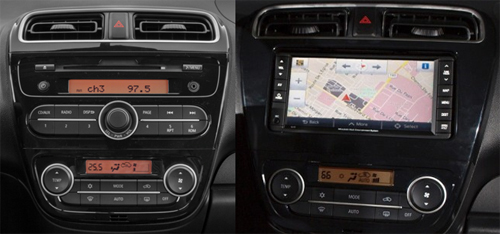
2015 Mitsubishi Mirage Audio Wiring Radio Diagram Schematic Colors – Aftermarket Stereo Installation Help
Car Radio Constant 12v+ Wire: White @ Pin 10 Radio Harness
Car Stereo Ground Wire: Black @ Pin 20 Radio Harness
Car Radio Ignition Switched Wire: Blue @ Pin 1 Radio Harness
Car Radio Illumination Wire: Gray @ Radio Harness
Car Radio Dimmer Wire: Light Blue @ Radio Harness
Car Stereo Power Antenna: N/A
Car Radio Amp Turn On Wire: N/A
Reverse Trigger: Dark Blue – Pin 7 @ Main Radio Harness
Left Front Speaker Wire (+) Positive: Red
Left Front Speaker Wire (-) Negative: Green
Right Front Speaker Wire (+) Positive: Brown
Right Front Speaker Wire (-) Negative: Purple
Left Rear Speaker Wire (+) Positive: Green
Left Rear Speaker Wire (-) Negative: White
Right Rear Speaker Wire (+) Positive: Brown
Right Rear Speaker Wire (-) Negative: Gray
SPEAKER WIRE COLORS AT THE SPEAKERS IN THE DOORS
Left Front Door Speaker Wire (+) Positive: Red
Left Front Door Speaker Wire (-) Negative: Yellow
Right Front Door Speaker Wire (+) Positive: Red
Right Front Door Speaker Wire (-) Negative: Blue
Left Rear Door Speaker Wire (+) Positive: Gray
Left Rear Door Speaker Wire (-) Negative: Light Blue
Right Rear Door Speaker Wire (+) Positive: Gray
Right Rear Door Speaker Wire (-) Negative: Light Blue
Center Channel Speaker Wire Positive / Negative: N/A
Subwoofer Speaker Wire Positive / Negative: N/A
Radio Size: Single or Double Din
Radio Removal Tools: – Dash Removal Plastic Pry Tools – Without OEM Nav: Use the pry tools to remove the vents above the radio. After that use a Phillips screwdriver the radio is held in with 2 screws. WITH OEM NAV: Use the pry tools to remove the vents and radio panel. After that use a Phillips screwdriver the radio is held in with 4 screws.
Keep in mind if you are installing a new radio in your Mirage you need the wiring harness, the antenna adapter, steering wheel control module, and the mounting kit as well.
REQUIRED PARTS FOR AFTERMARKET RADIO INSTALL
WIRING HARNESS:
WITHOUT OEM NAVIGATION: MOUNTING KIT FOR DOUBLE DIN AFTERMARKET RADIOS:
WITHOUT OEM NAVIGATION: MOUNTING KIT FOR SINGLE DIN AFTERMARKET RADIOS:
WITH OEM NAVIGATION: MOUNTING KIT FOR DOUBLE DIN AFTERMARKET RADIOS:
Use the OEM brackets attached to the factory nav unit along with the kit below to fill the gaps on the sides:
ANTENNA ADAPTER:
N/A
STEERING WHEEL CONTROLS ADAPTER:
Metra Axxess ASWC-1 Universal Steering Wheel Control Interface
ASWC-1 Installation Instructions:
Connect the red wire to the red switched lead from your aftermarket radio.
Connect the black wire to the black ground lead from your aftermarket radio.
Connect the black/green from the ASWC-1 to the pink wire in pin 9 or 2 depending which end you count from in the main radio connector.
Ground the purple wire in pin 19 or 11 depending which end you count from in the main radio connector.
AS of April 2015 the module will not auto detect you will have to follow the instructions to manually program but it works great after that!
FACTORY BACKUP REVERSE CAMERA INTEGRATION:
If you want the OEM camera to display on your aftermarket navigation, it runs off of 6v so you will need the below 5v adapter and a female adapter to hardwire it behind the radio. The camera wires are in a 5-pin plug behind the radio. For camera power you want to supply 6v from the adapters below to the purple wire and then ground the light blue and red wires.
For the video signal itself grab a bulk rca video cable below and cut it in half. Strip the ends and you’ll have the center conductor and shield. Connect the center conductor to the video positive which is black in the 5-pin plug. Connect the shield to the gray wire in the 5-pin plug.
SPEAKER WIRING ADAPTERS:
N/A
RECOMMENDED TOOLS FOR THE INSTALL – SAME ONES THE PROS USE!
– Gardner Bender Auto Wire Stripper
It is more helpful if you have actual pictures of the wiring harness with details, thanks
I just finished the install of the stock backup camera. I have a Kenwood DDX9702S. I purchased a Sirius XM 5V PowerConnect Vehicle Power Adapter and a Cigarette Lighter Socket. I had a video cable I cut in half. I already had an aftermarket camera but I wanted to see if this would work. I did everything as mentioned on here but I had already ran a wire from the right rear reverse light which is red/blue all the way to the back of the stereo because of the aftermarket camera. I left it hooked to my purple with white reverse wire on the back of the head unit. Since the head unit was out I took off the stock cigarette lighter plug through the opening where the head unit is. I spliced the wires together and installed the cigarette lighter plug. Then I plugged in the Sirius XM 5V PowerConnect Vehicle Power Adapter. I put electrical tape around it so it won’t come loose. Everything is hidden and I like that. It works perfectly fine. The only thing I did was turn off the guide lines on my head unit because I had all kinds of guide lines from the stock camera and the head unit. I hope this helps some of you out there.