Here is the audio stereo radio wiring information for your 2008 Ford Explorer with the standard or amplified systems. It will be useful when installing a stereo sound system, aftermarket headunit radio, or other automotive accessories. Make sure to grab the appropriate tools to test all the wires in your Explorer. Please check it over and use it as a GUIDE only to help you locate the appropriate wires. This schematic is provided free of charge and may not be 100% accurate. Failure to properly test all the wires may lead to vehicle or bodily damage. All information is provided as-is and accuracy is not guaranteed.
If you find any conflicting info please leave a comment with what you found in your 2008 Ford Explorer. If you don’t see the audio radio wiring diagram you need comment and we will try to add it ASAP. Thanks for looking!
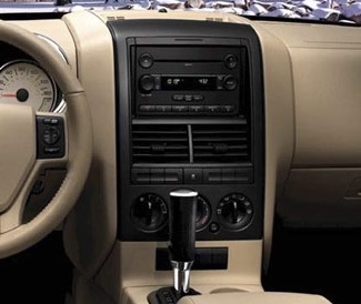
2008 Ford Explorer Audio Wiring Radio Diagram Schematic Colors – Aftermarket Stereo DIY Installation Help
Car Radio Constant 12v+ Wire: Blue/Red @ Radio Harness
Car Stereo Ground Wire: Black/Blue @ Radio Harness
Car Radio Ignition Switched Wire: Green/White @ Radio Harness
Car Radio Illumination Wire: Light Blue/White (+) @ Driver Kick Harness to Rear
Car Radio Dimmer Wire: N/A
Car Radio Amp Turn On Wire: Yellow/Purple @ Radio Harness
Car Stereo Power Antenna: N/A
Reverse Trigger: Brown/Blue (+) @ Driver Kick Harness to Rear
Parking Brake E-Brake Trigger: Gray/Blue (-) @ E-Brake Switch
Left Front Speaker Wire (+) Positive: White
Left Front Speaker Wire (-) Negative: White/Brown
Right Front Speaker Wire (+) Positive: White/Purple
Right Front Speaker Wire (-) Negative: White/Orange
Left Rear Speaker Wire (+) Positive: White/Green
Left Rear Speaker Wire (-) Negative: Brown/Yellow
Right Rear Speaker Wire (+) Positive: Brown/White
Right Rear Speaker Wire (-) Negative: Brown/Blue
Subwoofer Speaker Wire Positive / Negative: Purple/Green / Green/White
Center Channel Speaker Wire Positive / Negative: N/A
Radio Size: Single or Double Din
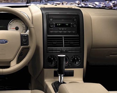
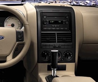
Radio Removal Tools: – Dash Removal Plastic Pry Tools – Open the center console lid and remove 2 7mm screws that hold the gear shift/cup holder panel in. Then pop that panel unplug any electrical connectors and remove it. Now starting at the top using the tools above pop the entire radio / climate control bezel off. There are no screws holding that panel on. Set the ebrake as you’ll probably have to put the shifter in a lower gear to remove that panel. Carefully unplug the airbag connector at the top and you can set that panel to the side of the console or unplug all the connectors and completely remove it. The radio is then held in with (4) 7mm screws.
Keep in mind if you are installing a new radio in your Explorer you need the wiring harness, the antenna adapter, and the mounting kit as well.
REQUIRED PARTS FOR AFTERMARKET RADIO INSTALL
WIRING HARNESS WITH FACTORY AMP:
This will keep your factory sub working as well.
The OEM amp turns on with 5v instead of 12v. A standard aftermarket radio uses 12v which will cause a loud pop when the amp turns on or off. Use the following adapter to drop the voltage down and get rid of the annoying turn on pop:
WIRING HARNESS WITHOUT FACTORY AMP:
MOUNTING KIT FOR DOUBLE DIN AFTERMARKET RADIOS:
MOUNTING KIT FOR SINGLE DIN AFTERMARKET RADIOS:
ANTENNA ADAPTER:
OEM AUX AUXILLIARY PORT RETENTION:
Use this to keep your OEM aux jack working with the new radio:
OEM AUX LEFT (+) Positive: Blue
OEM AUX LEFT (-) Positive: Yellow/Green
OEM AUX RIGHT (+) Positive: Blue/Green
OEM AUX RIGHT (-) Positive: White/Green
STEERING WHEEL CONTROL INTERFACE:
Use this to keep your steering wheel controls working with your new aftermarket radio.
REAR SEAT DVD RETENTION / RSE:
If your Explorer has the OEM overhead DVD system you will need the following harness to keep it functional with your new aftermarket radio:
SPEAKER WIRING ADAPTERS FOR AFTERMARKET SPEAKER INSTALL:
If doing front and rear speakers order 2 of these.
SPEAKER MOUNTING ADAPTERS FOR AFTERMARKET SPEAKER INSTALL:
If replacing the OEM 6×8″ speakers with 6.5″. If doing front and rear speakers order 2 of these.
RECOMMENDED TOOLS FOR THE INSTALL – SAME ONES THE PROS USE!
– Klein Wire Cutters / Crimpers
– Dash Removal Plastic Pry Tools