Tag Archives: 2005

Toyota Celica Fog Foglights on with DRL Park Lights Wiring Install Colors Diagram Schematic

Want to put your foglights on in your 2000 2001 2002 2003 2004 Toyota Celica without having to have your headlights on? There is a vehicle easy way to change it to allow you to put your fogs on with your parking lights or whenever you want! Make sure to grab the appropriate tools to test all the wires in your Celica. Please check it over and use it as a GUIDE only to help you locate the appropriate wires. This schematic is provided free of charge and may not be 100% accurate. Failure to properly test all the wires may lead to vehicle or bodily damage. All information is provided as-is and accuracy is not guaranteed.

Toyota Celica Fog Foglights on with DRL Park Lights Wiring Install Colors Diagram Schematic

If you find any conflicting info please leave a comment with what you found in your 2000 – 2004 Toyota Celica. If you don’t see the audio radio wiring diagram you need comment and we will try to add it ASAP. Thanks for looking!

2000 2001 2002 2003 2004 Toyota Celica Foglights on with Parking Lights Mod DIY Help

Car Headlight Wire: Red/White x 2 @ Foglight Relay
Car Parking Light Wire: Green (+) @ Cigarette Lighter

This mod is a lot easier than it sounds. So for starters the OEM foglight relay is in the drivers kick panel. Remove the kick panel and you’ll see some connectors and relays. The relay for the fogs is near the top square black going into a brown looking connector. Put your finger on it turn the ignition on, headlights on, then turn your foglights on and off and you can feel/hear it click. Turn everything off then unplug the relay. Next release the brown connector so you can get access to the wires at the rear of the connector.

Once you see the wires it’s simple you have 4 spots. All you need to be concerned with are the 2 red/white wires which go into the same pin. Now CUT both red/white wires giving yourself room to connect to either side or reconnect should you want to put everything back to stock. Now strip the ends of both red/white wires on the vehicle side NOT the relay connector side. Connect those 2 red/white wires together and tape them up. Now you are left with the 2 red/white wires going in to the connector. Strip those two and connect them together as well. Now you have some options:

– Option 1: Connect those 2 red/white wires to a CONSTANT source of power, such as the white wire at the ignition switch. This will give you complete control over your foglights to turn them on/off whenever you want independent of anything else. The downside if you leave them on they won’t turn off and will kill your battery.

– Option 2: Connect those 2 red/white wires to an IGNITION source of power, such as the blue/red wire at the ignition switch. This will give you complete control over your foglights as long as the key is turned on – doesn’t matter if you have headlights or anything on. When you turn the key off your foglights will shut off regardless of if you turn the foglight switch itself off.

– Option 3: Connect those 2 red/white wires to the PARKING light wire which is GREEN at the cigarette lighter connector. This will allow you to turn your fogs on with your parking lights and not require the headlights on. Turn your lights off, your foglights go off.

RECOMMENDED TOOLS FOR THE INSTALL – SAME ONES THE PROS USE!

– Klein Wire Cutters / Crimpers

– Dash Removal Plastic Pry Tools
– Gardner Bender Auto Wire Stripper

– Install Bay Butt Connectors

– 3M Electrical Tape

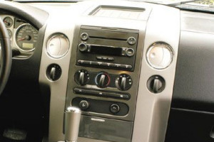
2005 Ford F-150 Audio Wiring Radio Diagram Schematic Colors

Here is the stereo radio wiring information for your 2005 Ford F-150 F150 body with the standard or amplified systems. It will be useful when installing an aftermarket radio, sound stereo system, or other automotive accessories. Make sure to grab the appropriate tools to test all the wires in your F-150 Pickup. Please check it over and use it as a GUIDE to help you locate the appropriate wires. This schematic is provided free of charge and may not be 100% accurate. Failure to properly test all the wires may lead to vehicle or bodily damage. All information is provided as-is and accuracy is not guaranteed.

2005 Ford F-150 Audio Radio Wiring

If you find any conflicting info please leave a comment with what you found in your Ford F-150. If you don’t see the audio radio wiring diagram you need comment and we will try to add it ASAP. Thanks for looking!

2005 Ford F-150 & FX4 Audio Wiring Radio Diagram Schematic Colors

Car Radio Constant 12v+ Wire: Light Green/Violet
Car Stereo Ground Wire: Black/Green or Black
Car Radio Ignition Switched Wire: Light Green/Yellow or Pink/Black @ Radio Harness

Car Stereo VSS Speed Wire: Gray/Black @ Main Radio Plug
Car Stereo Reverse Wire + : Pink/Black or Green/Yellow @ Driver door sill harness
Car Stereo Dimmer Wire: Light Blue/Red @ Main Radio Harness
Car Radio Illumination Wire: Brown (Park Lights) @ Driver door sill harness
Car Stereo Power Antenna:
Car Radio Amp Turn On Wire: Dark Green/Violet @ Smaller Amp Plug behind radio

Left Front Speaker Wire (+) Positive: Orange/Light Green
Left Front Speaker Wire (-) Negative: Light Blue/White
Right Front Speaker Wire (+) Positive: White/Light Green
Right Front Speaker Wire (-) Negative: Dark Green/Orange

Left Rear Speaker Wire (+) Positive: Gray/Light Blue
Left Rear Speaker Wire (-) Negative: Tan/Yellow
Right Rear Speaker Wire (+) Positive: Orange/Red
Right Rear Speaker Wire (-) Negative: Brown/Pink

Center Channel Speaker Wire Positive / Negative: N/A

Subwoofer Speaker Wire Positive / Negative: Brown/Orange & Red/Black

Radio Size: Single or Double Din

Radio Removal: Using plastic bezel removal tools carefully pop the radio bezel from the dash. Unplug all the connectors and remove the dash bezel. The radio is then held in with 4 7mm screws.

Keep in mind if you are installing a new radio you need the radio removal keys, the wiring harness, the antenna adapter, and the mounting kit as well. During installation we recommend removing some of the plastic behind the OEM radio to help fit the new aftermarket radio all the way in the dash.

REQUIRED PARTS FOR AFTERMARKET RADIO INSTALL

WIRING HARNESS WITHOUT OEM SUBWOOFER:

WIRING HARNESS WITH OEM SUB WOOFER:

MOUNTING KIT FOR DOUBLE DIN AFTERMARKET RADIOS:

MOUNTING KIT FOR SINGLE DIN AFTERMARKET RADIOS:

OEM AMP TURN ON POP FIX :

If you’re experiencing a loud pop through your F150 sub when the radio turns on and off, this interface will correct the issue by stepping down the turn on voltage to your OEM amplifier.

CUSTOM UNDER SEAT BOX ENCLOSURE FOR ADDING AFTERMARKET SUB WOOFER:

ANTENNA ADAPTER FOR INSTALL:

Only required for trucks 2007 and up. No adapter required for pre 2007 Ford F-150

SPEAKER WIRING ADAPTER FOR INSTALL:

Use these if you don’t want to tap in or cut off your existing speaker connectors. They plug right in then right on to the new speaker making installation a breeze. Order quantity 2 if doing front and rear speakers.

STEERING WHEEL CONTROLS ADAPTER:
Metra Axxess ASWC-1 Universal Steering Wheel Control Interface

RECOMMENDED TOOLS FOR THE INSTALL – SAME ONES THE PROS USE!

– 3M Electrical Tape

– Install Bay Butt Connectors

– Klein Wire Cutters / Crimpers

– Gardner Bender Auto Wire Stripper

– Dash Removal Plastic Pry Tools

2005 Audi A4 Car Radio Audio Stereo Wiring Diagram Colors

Here is the stereo radio wiring information for your 2005 Audi B6 / B7 A4 with the standard, symphony, or Bose systems. It will be useful when installing an aftermarket radio, sound stereo system, or other automotive accessories. Make sure to grab the appropriate tools to test all the wires in your A4. Please check it over and use it as a GUIDE to help you locate the appropriate wires. This schematic is provided free of charge and may not be 100% accurate. Failure to properly test all the wires may lead to vehicle or bodily damage. All information is provided as-is and accuracy is not guaranteed.

If you find any conflicting info please leave a comment with what you found in your Audi B6 / B7 A4. If you don’t see the wiring diagram you need comment and we will try to add it ASAP. Thanks for looking!

Keep in mind if you are installing a new radio you may need the radio removal  keys, the wiring harness, the antenna adapter, and the mounting kit as well. See the links below to purchase these items.

2005 Audi A4 Car Audio Stereo Radio Wiring Diagram Schematic Colors

Car Radio Constant 12v+ Wire: Red/Blue
Car Stereo Ground Wire: Brown
Car Radio Ignition Switched Wire: Not available Grab @ Fusebox

Car Stereo Dimmer Wire: Gray/Blue @ Radio with Nav Only or Cigarette Lighter
Car Radio Illumination Wire: Gray/Blue @ Radio with Nav Only or Cigarette Lighter
Car Stereo Power Antenna: N/A
Car Radio Amp Turn On Wire: White @ Radio

Left Front Speaker Wire (+) Positive: Brown/Green
Left Front Speaker Wire (-) Negative: Blue/Yellow
Right Front Speaker Wire (+) Positive: Brown/Blue
Right Front Speaker Wire (-) Negative: Green/Blue

Left Rear Speaker Wire (+) Positive: Brown/Yellow
Left Rear Speaker Wire (-) Negative: Red/Yellow
Right Rear Speaker Wire (+) Positive: Brown/Black
Right Rear Speaker Wire (-) Negative: Red/Green

Center Channel Speaker Wire Positive / Negative: Tied in with front speakers.

Subwoofer Speaker Wire Positive / Negative: Red/Gray Brown/Gray @ Amp

Front Speaker Size: N/A

Rear Speaker Size: N/A

Amp Amplifier Location: Passenger side of trunk behind carpet
Radio Removal: VW / AUDI / MERCEDES Keys

AFTERMARKET RADIO MOUNTING KIT SINGLE OR DOUBLE DIN:

Audi A4 02 – 08 SDIN – DDIN kit (Matte Black)

AFTERMARKET RADIO WIRING HARNESS:

Metra 70-1787 Radio Wiring Harness for VW/Audi Bose Integration 1993-2007

AFTERMARKET RADIO ANTENNA ADAPTER:

Metra 40-VW54 VW Amplified Antenna Adapter

STEERING WHEEL CONTROLS ADAPTER:

Metra Axxess ASWC-1 Universal Steering Wheel Control Interface

RECOMMENDED TOOLS FOR THE INSTALL – SAME ONES THE PROS USE!

– Klein Wire Cutters / Crimpers

– Gardner Bender Auto Wire Stripper

– Dash Removal Plastic Pry Tools

– 3M Electrical Tape

– Install Bay Butt Connectors