Tag Archives: stereo

2002 Chevy Cavalier Headunit Stereo Audio Radio Wiring Install Colors Diagram Schematic

Here is the audio stereo radio wiring information for your 2002 Chevrolet Cavalier with the standard or Monsoon system. It will be useful when installing an aftermarket headunit, stereo sound system, new radio, or other automotive accessories. Make sure to grab the appropriate tools to test all the wires in your Chevy Cavalier. Please check it over and use it as a GUIDE only to help you locate the appropriate wires. This schematic is provided free of charge and may not be 100% accurate. Failure to properly test all the wires may lead to vehicle or bodily damage. All information is provided as-is and accuracy is not guaranteed.

2001 Chevy Cavalier Headunit Audio Radio Wiring Install Diagram Schematic Colors
2002 Chevy Cavalier Headunit Audio Radio Wiring Install Diagram Schematic Colors

If you find any conflicting info please leave a comment with what you found in your 2002 Chevrolet Cavlalier. If you don’t see the audio radio wiring diagram you need comment and we will try to add it ASAP. Thanks for looking!

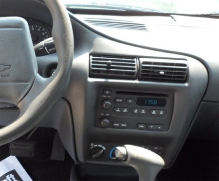
2002 Chevrolet Cavalier Radio Audio Wiring Diagram Schematic Colors – Aftermarket Stereo DIY Installation Help

Car Radio Constant 12v+ Wire: Orange @ Radio Harness
Car Stereo Ground Wire: Black @ Radio Harness
Car Radio Ignition Switched Wire: Class II Data – Use proper harness

Car Radio Dimmer Wire: Gray (+) @ Radio Harness
Car Radio Illumination Wire: Brown (+) @ Radio Harness

Car Radio Amp Turn On Wire: Pink @ Radio Harness when equipped
Car Stereo Power Antenna: N/A

Reverse Trigger: Light Green (+) Driver kick harness to rear
Parking Brake E-Brake Trigger: Light Blue (-) @ e-brake

Left Front Speaker Wire (+) Positive: Tan
Left Front Speaker Wire (-) Negative: Gray
Right Front Speaker Wire (+) Positive: Light Green
Right Front Speaker Wire (-) Negative: Dark Green

Left Rear Speaker Wire (+) Positive: Brown
Left Rear Speaker Wire (-) Negative: Yellow
Right Rear Speaker Wire (+) Positive: Dark Blue
Right Rear Speaker Wire (-) Negative: Light Blue

Center Channel Speaker Wire Positive / Negative: N/A

Subwoofer Speaker Wire Positive / Negative: N/A

Radio Size: Single Din or Double Din – will require some minor trimming of plastic behind the OEM radio.

Radio Removal Tools: – Dash Removal Plastic Pry Tools

REQUIRED PARTS FOR AFTERMARKET RADIO INSTALL

WIRING HARNESS:

This harness is for base / non-monsoon / non-premium sound systems and will keep your safety chimes functioning, provide a switched turn on wire, and keep the retained accessory system working. It will NOT retain OnStar or work with the Monsoon system.

If you have the Monsoon or premium sound, use the harness below:

REPAIR REVERSE WIRING HARNESS:

N/A

MOUNTING KIT FOR SINGLE DIN AFTERMARKET RADIOS:

MOUNTING KIT FOR DOUBLE DIN AFTERMARKET RADIOS:

ANTENNA ADAPTER:

OEM AUX AUXILLIARY PORT RETENTION:

N/A

STEERING WHEEL CONTROL INTERFACE:

Use this to keep your steering wheel controls working with your new aftermarket radio. All wires connected at the back of the OEM radio:

SPEAKER WIRING ADAPTERS FOR AFTERMARKET SPEAKER INSTALL:

The adapters below will allow you to install a 5 1/4″ or 6.5″ speaker in place of the OEM 4×6″ speakers in the front doors.

RECOMMENDED TOOLS FOR THE INSTALL – SAME ONES THE PROS USE!

– Klein Wire Cutters / Crimpers

– Dash Removal Plastic Pry Tools

– Gardner Bender Auto Wire Stripper

– Install Bay Butt Connectors

– 3M Electrical Tape

2001 Chevy Cavalier Headunit Audio Radio Wiring Install Diagram Schematic Colors

Here is the audio stereo radio wiring information for your 2001 Chevrolet Cavalier with the standard system. It will be useful when installing a stereo sound system, aftermarket headunit radio, or other automotive accessories. Make sure to grab the appropriate tools to test all the wires in your Cavalier. Please check it over and use it as a GUIDE only to help you locate the appropriate wires. This schematic is provided free of charge and may not be 100% accurate. Failure to properly test all the wires may lead to vehicle or bodily damage. All information is provided as-is and accuracy is not guaranteed.

2001 Chevrolet Cavalier Audio Wiring Diagram Stereo Install

If you find any conflicting info please leave a comment with what you found in your 2001 Chevrolet Cavlalier. If you don’t see the audio radio wiring diagram you need comment and we will try to add it ASAP. Thanks for looking!

2001 Chevrolet Cavalier Audio Wiring Radio Diagram Schematic Colors – Aftermarket Stereo DIY Installation Help

Car Radio Constant 12v+ Wire: Orange @ Radio Harness
Car Stereo Ground Wire: Black @ Radio Harness
Car Radio Ignition Switched Wire: Class II Data – Use proper harness

Car Radio Illumination Wire: Brown (+) @ Radio Harness
Car Radio Dimmer Wire: Gray (+) @ Radio Harness

Car Radio Amp Turn On Wire: Pink @ Radio Harness if equipped
Car Stereo Power Antenna: N/A

Reverse Trigger: N/A
Parking Brake E-Brake Trigger: N/A

Left Front Speaker Wire (+) Positive: Tan
Left Front Speaker Wire (-) Negative: Gray
Right Front Speaker Wire (+) Positive: Light Green
Right Front Speaker Wire (-) Negative: Dark Green

Left Rear Speaker Wire (+) Positive: Brown
Left Rear Speaker Wire (-) Negative: Yellow
Right Rear Speaker Wire (+) Positive: Dark Blue
Right Rear Speaker Wire (-) Negative: Light Blue

Subwoofer Speaker Wire Positive / Negative: N/A

Center Channel Speaker Wire Positive / Negative: N/A

Radio Size: Single Din or Double Din

Radio Removal Tools: – Dash Removal Plastic Pry Tools

REQUIRED PARTS FOR AFTERMARKET RADIO INSTALL

WIRING HARNESS:

This harness is for base / non-monsoon / non-premium sound systems and will keep your safety chimes functioning, provide a switched turn on wire, and keep the retained accessory system working. It will NOT retain OnStar or work with the Monsoon system.

If you have the Monsoon or premium sound, use the harness below:

REPAIR REVERSE WIRING HARNESS:

N/A

MOUNTING KIT FOR DOUBLE DIN AFTERMARKET RADIOS:

MOUNTING KIT FOR SINGLE DIN AFTERMARKET RADIOS:

ANTENNA ADAPTER:

OEM AUX AUXILLIARY PORT RETENTION:

N/A

STEERING WHEEL CONTROL INTERFACE:

Use this to keep your steering wheel controls working with your new aftermarket radio. All wires connected at the back of the OEM radio:

SPEAKER WIRING ADAPTERS FOR AFTERMARKET SPEAKER INSTALL:

The adapters below will allow you to install a 5 1/4″ or 6.5″ speaker in place of the OEM 4×6″ speakers in the front doors.

RECOMMENDED TOOLS FOR THE INSTALL – SAME ONES THE PROS USE!

– Klein Wire Cutters / Crimpers

– Dash Removal Plastic Pry Tools

– Gardner Bender Auto Wire Stripper

– Install Bay Butt Connectors

– 3M Electrical Tape

1997 Buick Century Headunit Audio Radio Wiring Install Diagram Schematic Colors

Here is the audio stereo radio wiring information for your 1997 Buick Century with the standard or Concert system. It will be useful when installing a stereo sound system, aftermarket headunit radio, or other automotive accessories. Make sure to grab the appropriate tools to test all the wires in your Century. Please check it over and use it as a GUIDE only to help you locate the appropriate wires. This schematic is provided free of charge and may not be 100% accurate. Failure to properly test all the wires may lead to vehicle or bodily damage. All information is provided as-is and accuracy is not guaranteed.

1997 Buick Century Headunit Audio Radio Wiring Install Diagram Colors Schematic

If you find any conflicting info please leave a comment with what you found in your 1997 Buick Century. If you don’t see the audio radio wiring diagram you need comment and we will try to add it ASAP. Thanks for looking!

1997 Buick Century Audio Wiring Radio Diagram Schematic Colors – Aftermarket Stereo DIY Installation Help

Car Radio Constant 12v+ Wire: Orange @ Radio Harness
Car Stereo Ground Wire: Black/White @ Radio Harness
Car Radio Ignition Switched Wire: Yellow @ Radio Harness

Car Radio Illumination Wire: Gray (+) @ Radio Harness
Car Radio Dimmer Wire: N/A

Car Radio Amp Turn On Wire: Dark Green @ Radio Harness
Car Stereo Power Antenna: Same As Above

Reverse Trigger: N/A
Parking Brake E-Brake Trigger: N/A

Left Front Speaker Wire (+) Positive: Tan
Left Front Speaker Wire (-) Negative: Gray
Right Front Speaker Wire (+) Positive: Light Green
Right Front Speaker Wire (-) Negative: Dark Green

Left Rear Speaker Wire (+) Positive: Brown
Left Rear Speaker Wire (-) Negative: Yellow
Right Rear Speaker Wire (+) Positive: Dark Blue
Right Rear Speaker Wire (-) Negative: Light Blue

Subwoofer Speaker Wire Positive / Negative: N/A

Center Channel Speaker Wire Positive / Negative: N/A

Radio Size: Single or Double Din

Radio Removal Tools: – Dash Removal Plastic Pry Tools

REQUIRED PARTS FOR AFTERMARKET RADIO INSTALL

WIRING HARNESS:

MOUNTING KIT FOR DOUBLE DIN AFTERMARKET RADIOS:

MOUNTING KIT FOR SINGLE DIN AFTERMARKET RADIOS:

ANTENNA ADAPTER:

OEM AUX AUXILLIARY PORT RETENTION:

N/A

STEERING WHEEL CONTROL INTERFACE:

Use this to keep your steering wheel controls working with your new aftermarket radio. All wires connected at the back of the OEM radio:

SPEAKER WIRING ADAPTERS FOR AFTERMARKET SPEAKER INSTALL:

If doing front and rear speakers order 2 of these.

RECOMMENDED TOOLS FOR THE INSTALL – SAME ONES THE PROS USE!

– Klein Wire Cutters / Crimpers

– Dash Removal Plastic Pry Tools

– Gardner Bender Auto Wire Stripper

– Install Bay Butt Connectors

– 3M Electrical Tape

2006 Mini Cooper S Headunit Audio Radio Wiring Install Diagram Schematic Colors

Here is the audio stereo radio wiring information for your 2006 Mini Cooper S Convertible with the standard not the Harmon Kardon amplified system. It will be useful when installing a stereo sound system, aftermarket headunit radio, or other automotive accessories. Make sure to grab the appropriate tools to test all the wires in your Mini. Please check it over and use it as a GUIDE only to help you locate the appropriate wires. This schematic is provided free of charge and may not be 100% accurate. Failure to properly test all the wires may lead to vehicle or bodily damage. All information is provided as-is and accuracy is not guaranteed.

2006 Mini Cooper S Headunit Audio Radio Wiring Install Diagram Colors Schematic

If you find any conflicting info please leave a comment with what you found in your 2006 Mini Cooper S. If you don’t see the audio radio wiring diagram you need comment and we will try to add it ASAP. Thanks for looking!

2006 Mini Cooper S Audio Wiring Radio Diagram Schematic Colors – Aftermarket Stereo DIY Installation Help

Car Radio Constant 12v+ Wire: Red/Brown@ Radio Harness
Car Stereo Ground Wire: Brown @ Radio Harness
Car Radio Ignition Switched Wire: Purple/Blue @ Radio Harness

Car Radio Illumination Wire: Gray/Red (+) @ Radio Harness
Car Radio Dimmer Wire: N/A

Car Radio Amp Turn On Wire: White @ Radio Harness
Car Stereo Power Antenna: Same As Above

Reverse Trigger: Blue/Yellow (+) @ Driver Kick Harness to Rear
Parking Brake E-Brake Trigger: Blue/Brown w/ Yellow Dots (-) @ E-Brake Switch

Left Front Speaker Wire (+) Positive: Yellow/Red
Left Front Speaker Wire (-) Negative: Yellow/Brown
Right Front Speaker Wire (+) Positive: Brown/Black (Yellow/Red @ Speaker)
Right Front Speaker Wire (-) Negative: Blue/Brown Yellow/Brown @ Speaker)

Left Rear Speaker Wire (+) Positive: Blue/Black
Left Rear Speaker Wire (-) Negative: Blue/Brown
Right Rear Speaker Wire (+) Positive: Yellow/Black
Right Rear Speaker Wire (-) Negative: Yellow/Brown

Subwoofer Speaker Wire Positive / Negative: N/A

Center Channel Speaker Wire Positive / Negative: N/A

Radio Size: Single

Radio Removal Tools: – Dash Removal Plastic Pry Tools – Remove 1 screw from inside each cup holder in front of the shifter. Using the plastic pry tools above pry out the power mirror switch assembly behind the shifter and remove 2 screws underneath. Pull from the top of the panel under the steering column and unhook it. The bottom hinges but can come out as well. Remove 2 torx screws in pillar to the left of the radio. Open the glovebox. Remove 2 torx screws from the pillar to the right of the radio. Now move the pillars around enough that you can push the tops left or right to gain access to 4 torx screws holding the radio in. Remove and pull the radio out. Disconnect the plug and antenna. Keep in mind if you are installing a new radio in your Explorer you need the wiring harness, the antenna adapter, and the mounting kit as well.

REQUIRED PARTS FOR AFTERMARKET RADIO INSTALL

WIRING HARNESS WITHOUT FACTORY AMP:

MOUNTING KIT FOR DOUBLE DIN AFTERMARKET RADIOS:

N/A

MOUNTING KIT FOR SINGLE DIN AFTERMARKET RADIOS:

ANTENNA ADAPTER:

OEM AUX AUXILLIARY PORT RETENTION:

N/A

STEERING WHEEL CONTROL INTERFACE:

Use this to keep your steering wheel controls working with your new aftermarket radio. All wires connected at the back of the OEM radio:

You may alternately use this instead it is a bit cheaper but you have to cut and connect to a wire at the steering column instead of behind the radio:

SPEAKER WIRING ADAPTERS FOR AFTERMARKET SPEAKER INSTALL:

If doing front and rear speakers order 2 of these.

SPEAKER MOUNTING ADAPTERS FOR AFTERMARKET SPEAKER INSTALL:

If replacing the OEM speakers with 5 1/4″ – 6″ speakers these adapters will bolt right in the front:

NOTE – THESE WILL NOT FIT 6.5″ SPEAKERS!

IF INSTALLING 6.5″ SPEAKERS, YOU WILL HAVE TO MAKE NEW MOUNTING HOLES BUT THESE ADAPTERS WILL WORK AND GIVE A LITTLE EXTRA DEPTH:

RECOMMENDED TOOLS FOR THE INSTALL – SAME ONES THE PROS USE!

– Klein Wire Cutters / Crimpers

– Dash Removal Plastic Pry Tools

– Gardner Bender Auto Wire Stripper

– Install Bay Butt Connectors

– 3M Electrical Tape

1994 Mazda Miata Vent Removal Headunit Audio Radio Wiring Install Diagram Schematic Colors

Here is the audio stereo radio wiring information for your 1994 Mazda Miata with the standard or amplified systems. It will be useful when installing a stereo sound system, aftermarket headunit radio, or other automotive accessories. Make sure to grab the appropriate tools to test all the wires in your Miata. Please check it over and use it as a GUIDE only to help you locate the appropriate wires. This schematic is provided free of charge and may not be 100% accurate. Failure to properly test all the wires may lead to vehicle or bodily damage. All information is provided as-is and accuracy is not guaranteed.

1994 Mazda Miata Vent Removal Headunit Audio Radio Wiring Install Diagram Schematic Colors

If you find any conflicting info please leave a comment with what you found in your 1994 Mazda Miata. If you don’t see the audio radio wiring diagram you need comment and we will try to add it ASAP. Thanks for looking!

1994 Mazda Miata Audio Wiring Radio Diagram Schematic Colors – Aftermarket Stereo DIY Installation Help

Car Radio Constant 12v+ Wire: Blue/Red @ Radio Harness
Car Stereo Ground Wire: Black @ Back of Radio
Car Radio Ignition Switched Wire: Blue/Black @ Radio Harness

Car Radio Illumination Wire: Red/Black @ Radio Harness
Car Radio Dimmer Wire: N/A

Car Radio Amp Turn On Wire: Light Green/Yellow @ Radio Harness
Car Stereo Power Antenna: N/A

Left Front Headrest Speaker Wire (+) Positive: Red/Yellow
Left Front Headrest Speaker Wire (-) Negative: Blue/Orange
Right Front Headrest Speaker Wire (+) Positive: Red/Blue
Right Front Headrest Speaker Wire (-) Negative: Blue/White

Left Front Door Speaker Wire (+) Positive: Red/Green
Left Front Door Speaker Wire (-) Negative: Red/White
Right Front Door Speaker Wire (+) Positive: Brown/White
Right Front Door Speaker Wire (-) Negative: Brown/Blue

Radio Removal Tools: Plastic Vent Removal Tools
– Open the center console lid and remove 2 screws at the bottom of the console. Remove 1 screw under the cup holder on the console. Remove 1 screw from each side of the center console near the shifter. Unscrew the shift knob for manual trans. Pull the center console and unplug the connectors make sure to feed the gas door levers through the hole inside the console. Remove 1 screw at the bottom of the radio bezel. Using the plastic tools above and a scrap piece of wire pop the center console vents out. Remove 1 screw behind each vent. Now pop the radio bezel the radio is then held in with 4 screws.

Keep in mind if you are installing a new radio in your Miata you need the wiring harness and the mounting kit as well.

REQUIRED PARTS FOR AFTERMARKET RADIO INSTALL

WIRING HARNESS:

MOUNTING KIT FOR SINGLE DIN AFTERMARKET RADIOS:

ANTENNA ADAPTER:

N/A

OEM AUX AUXILLIARY PORT RETENTION:

N/A

STEERING WHEEL CONTROL INTERFACE:

N/A

RECOMMENDED TOOLS FOR THE INSTALL – SAME ONES THE PROS USE!

– Klein Wire Cutters / Crimpers

Car Audio Radio 4 in 1 Plastic Trim Molding Pry Bar Removal Tool Green

– Gardner Bender Auto Wire Stripper

– Install Bay Butt Connectors

– 3M Electrical Tape

2008 Ford Explorer Headunit Audio Radio Wiring Install Diagram Schematic Colors

Here is the audio stereo radio wiring information for your 2008 Ford Explorer with the standard or amplified systems. It will be useful when installing a stereo sound system, aftermarket headunit radio, or other automotive accessories. Make sure to grab the appropriate tools to test all the wires in your Explorer. Please check it over and use it as a GUIDE only to help you locate the appropriate wires. This schematic is provided free of charge and may not be 100% accurate. Failure to properly test all the wires may lead to vehicle or bodily damage. All information is provided as-is and accuracy is not guaranteed.

2008 Ford Explorer Headunit Audio Radio Wiring Install Diagram Colors Schematic

If you find any conflicting info please leave a comment with what you found in your 2008 Ford Explorer. If you don’t see the audio radio wiring diagram you need comment and we will try to add it ASAP. Thanks for looking!

2008 Ford Explorer Audio Wiring Radio Diagram Schematic Colors – Aftermarket Stereo DIY Installation Help

Car Radio Constant 12v+ Wire: Blue/Red @ Radio Harness
Car Stereo Ground Wire: Black/Blue @ Radio Harness
Car Radio Ignition Switched Wire: Green/White @ Radio Harness

Car Radio Illumination Wire: Light Blue/White (+) @ Driver Kick Harness to Rear
Car Radio Dimmer Wire: N/A

Car Radio Amp Turn On Wire: Yellow/Purple @ Radio Harness
Car Stereo Power Antenna: N/A

Reverse Trigger: Brown/Blue (+) @ Driver Kick Harness to Rear
Parking Brake E-Brake Trigger: Gray/Blue (-) @ E-Brake Switch

Left Front Speaker Wire (+) Positive: White
Left Front Speaker Wire (-) Negative: White/Brown
Right Front Speaker Wire (+) Positive: White/Purple
Right Front Speaker Wire (-) Negative: White/Orange

Left Rear Speaker Wire (+) Positive: White/Green
Left Rear Speaker Wire (-) Negative: Brown/Yellow
Right Rear Speaker Wire (+) Positive: Brown/White
Right Rear Speaker Wire (-) Negative: Brown/Blue

Subwoofer Speaker Wire Positive / Negative: Purple/Green / Green/White

Center Channel Speaker Wire Positive / Negative: N/A

Radio Size: Single or Double Din

Radio Removal Tools: – Dash Removal Plastic Pry Tools – Open the center console lid and remove 2 7mm screws that hold the gear shift/cup holder panel in. Then pop that panel unplug any electrical connectors and remove it. Now starting at the top using the tools above pop the entire radio / climate control bezel off. There are no screws holding that panel on. Set the ebrake as you’ll probably have to put the shifter in a lower gear to remove that panel. Carefully unplug the airbag connector at the top and you can set that panel to the side of the console or unplug all the connectors and completely remove it. The radio is then held in with (4) 7mm screws.

Keep in mind if you are installing a new radio in your Explorer you need the wiring harness, the antenna adapter, and the mounting kit as well.

REQUIRED PARTS FOR AFTERMARKET RADIO INSTALL

WIRING HARNESS WITH FACTORY AMP:

This will keep your factory sub working as well.

The OEM amp turns on with 5v instead of 12v. A standard aftermarket radio uses 12v which will cause a loud pop when the amp turns on or off. Use the following adapter to drop the voltage down and get rid of the annoying turn on pop:

WIRING HARNESS WITHOUT FACTORY AMP:

MOUNTING KIT FOR DOUBLE DIN AFTERMARKET RADIOS:

MOUNTING KIT FOR SINGLE DIN AFTERMARKET RADIOS:

ANTENNA ADAPTER:

OEM AUX AUXILLIARY PORT RETENTION:

Use this to keep your OEM aux jack working with the new radio:

OEM AUX LEFT (+) Positive: Blue
OEM AUX LEFT (-) Positive: Yellow/Green
OEM AUX RIGHT (+) Positive: Blue/Green
OEM AUX RIGHT (-) Positive: White/Green

STEERING WHEEL CONTROL INTERFACE:

Use this to keep your steering wheel controls working with your new aftermarket radio.

REAR SEAT DVD RETENTION / RSE:

If your Explorer has the OEM overhead DVD system you will need the following harness to keep it functional with your new aftermarket radio:

SPEAKER WIRING ADAPTERS FOR AFTERMARKET SPEAKER INSTALL:

If doing front and rear speakers order 2 of these.

SPEAKER MOUNTING ADAPTERS FOR AFTERMARKET SPEAKER INSTALL:

If replacing the OEM 6×8″ speakers with 6.5″. If doing front and rear speakers order 2 of these.

RECOMMENDED TOOLS FOR THE INSTALL – SAME ONES THE PROS USE!

– Klein Wire Cutters / Crimpers

– Dash Removal Plastic Pry Tools

– Gardner Bender Auto Wire Stripper

– Install Bay Butt Connectors

– 3M Electrical Tape

2007 Ford Explorer Headunit Audio Wiring Radio Install Diagram Schematic Colors

Here is the audio stereo radio wiring information for your 2007 Ford Explorer with the standard or amplified systems. It will be useful when installing a stereo sound system, aftermarket headunit radio, or other automotive accessories. Make sure to grab the appropriate tools to test all the wires in your Explorer. Please check it over and use it as a GUIDE only to help you locate the appropriate wires. This schematic is provided free of charge and may not be 100% accurate. Failure to properly test all the wires may lead to vehicle or bodily damage. All information is provided as-is and accuracy is not guaranteed.

2005 Toyota Celica Headunit Audio Radio Wiring Install Diagram Colors Schematic
2007 Ford Explorer Headunit Audio Radio Wiring Install Diagram Colors Schematic

If you find any conflicting info please leave a comment with what you found in your 2007 Ford Explorer. If you don’t see the audio radio wiring diagram you need comment and we will try to add it ASAP. Thanks for looking!

2007 Ford Explorer Audio Wiring Radio Diagram Schematic Colors – Aftermarket Stereo DIY Installation Help

Car Radio Constant 12v+ Wire: Blue/Red @ Radio Harness
Car Stereo Ground Wire: Black/Blue @ Radio Harness
Car Radio Ignition Switched Wire: Green/White @ Radio Harness

Car Radio Illumination Wire: Light Blue/White (+) @ Driver Kick Harness to Rear
Car Radio Dimmer Wire: N/A

Car Radio Amp Turn On Wire: N/A
Car Stereo Power Antenna: N/A

Reverse Trigger: Brown/Blue (+) @ Driver Kick Harness to Rear
Parking Brake E-Brake Trigger: Gray/Blue (-) @ E-Brake Switch

Left Front Speaker Wire (+) Positive: White
Left Front Speaker Wire (-) Negative: White/Brown
Right Front Speaker Wire (+) Positive: White/Purple
Right Front Speaker Wire (-) Negative: White/Orange

Left Rear Speaker Wire (+) Positive: Brown/Green
Left Rear Speaker Wire (-) Negative: Brown/Yellow
Right Rear Speaker Wire (+) Positive: Brown/White
Right Rear Speaker Wire (-) Negative: Brown/Blue

Subwoofer Speaker Wire Positive / Negative: N/A

Center Channel Speaker Wire Positive / Negative: N/A

Radio Size: Single or Double Din

Radio Removal Tools: – Dash Removal Plastic Pry Tools – Open the center console lid and remove 2 7mm screws that hold the gear shift/cup holder panel in. Then pop that panel unplug any electrical connectors and remove it. Now starting at the top using the tools above pop the entire radio / climate control bezel off. There are no screws holding that panel on. Set the ebrake as you’ll probably have to put the shifter in a lower gear to remove that panel. Carefully unplug the airbag connector at the top and you can set that panel to the side of the console or unplug all the connectors and completely remove it. The radio is then held in with (4) 7mm screws.

Keep in mind if you are installing a new radio in your Explorer you need the wiring harness, the antenna adapter, and the mounting kit as well.

REQUIRED PARTS FOR AFTERMARKET RADIO INSTALL

WIRING HARNESS WITH FACTORY AMP:

This will keep your factory sub working as well.

The OEM amp turns on with 5v instead of 12v. A standard aftermarket radio uses 12v which will cause a loud pop when the amp turns on or off. Use the following adapter to drop the voltage down and get rid of the annoying turn on pop:

WIRING HARNESS WITHOUT FACTORY AMP:

MOUNTING KIT FOR DOUBLE DIN AFTERMARKET RADIOS:

MOUNTING KIT FOR SINGLE DIN AFTERMARKET RADIOS:

ANTENNA ADAPTER:

OEM AUX AUXILLIARY PORT RETENTION:

Use this to keep your OEM aux jack working with the new radio:

STEERING WHEEL CONTROL INTERFACE:

Use this to keep your steering wheel controls working with your new aftermarket radio.

REAR SEAT DVD RETENTION / RSE:

If your Explorer has the OEM overhead DVD system you will need the following harness to keep it functional with your new aftermarket radio:

SPEAKER WIRING ADAPTERS FOR AFTERMARKET SPEAKER INSTALL:

If doing front and rear speakers order 2 of these.

SPEAKER MOUNTING ADAPTERS FOR AFTERMARKET SPEAKER INSTALL:

If replacing the OEM 6×8″ speakers with 6.5″. If doing front and rear speakers order 2 of these.

RECOMMENDED TOOLS FOR THE INSTALL – SAME ONES THE PROS USE!

– Klein Wire Cutters / Crimpers

– Dash Removal Plastic Pry Tools

– Gardner Bender Auto Wire Stripper

– Install Bay Butt Connectors

– 3M Electrical Tape

2006 Ford Explorer Headunit Audio Radio Wiring Install Diagram Colors Schematic

Here is the audio stereo radio wiring information for your 2006 Ford Explorer with the standard or amplified systems. It will be useful when installing a stereo sound system, aftermarket headunit radio, or other automotive accessories. Make sure to grab the appropriate tools to test all the wires in your Explorer. Please check it over and use it as a GUIDE only to help you locate the appropriate wires. This schematic is provided free of charge and may not be 100% accurate. Failure to properly test all the wires may lead to vehicle or bodily damage. All information is provided as-is and accuracy is not guaranteed.

2006 Ford Explorer Headunit Audio Radio Wiring Install Diagram Colors Schematic

If you find any conflicting info please leave a comment with what you found in your 2006 Ford Explorer. If you don’t see the audio radio wiring diagram you need comment and we will try to add it ASAP. Thanks for looking!

2006 Ford Explorer Audio Wiring Radio Diagram Schematic Colors – Aftermarket Stereo DIY Installation Help

Car Radio Constant 12v+ Wire: Blue/Red @ Radio Harness
Car Stereo Ground Wire: Black/Blue @ Radio Harness
Car Radio Ignition Switched Wire: Green/White @ Radio Harness

Car Radio Illumination Wire: Light Blue/White (+) @ Driver Kick Harness to Rear
Car Radio Dimmer Wire: N/A

Car Radio Amp Turn On Wire: N/A
Car Stereo Power Antenna: N/A

Reverse Trigger: Brown/Blue (+) @ Driver Kick Harness to Rear
Parking Brake E-Brake Trigger: Gray/Blue (-) @ E-Brake Switch

Left Front Speaker Wire (+) Positive: White
Left Front Speaker Wire (-) Negative: White/Brown
Right Front Speaker Wire (+) Positive: White/Purple
Right Front Speaker Wire (-) Negative: White/Orange

Left Rear Speaker Wire (+) Positive: Brown/Green
Left Rear Speaker Wire (-) Negative: Brown/Yellow
Right Rear Speaker Wire (+) Positive: Brown/White
Right Rear Speaker Wire (-) Negative: Brown/Blue

Subwoofer Speaker Wire Positive / Negative: N/A

Center Channel Speaker Wire Positive / Negative: N/A

Radio Size: Single or Double Din

Radio Removal Tools: – Dash Removal Plastic Pry Tools – Open the center console lid and remove 2 7mm screws that hold the gear shift/cup holder panel in. Then pop that panel unplug any electrical connectors and remove it. Now starting at the top using the tools above pop the entire radio / climate control bezel off. There are no screws holding that panel on. Set the ebrake as you’ll probably have to put the shifter in a lower gear to remove that panel. Carefully unplug the airbag connector at the top and you can set that panel to the side of the console or unplug all the connectors and completely remove it. The radio is then held in with (4) 7mm screws.

Keep in mind if you are installing a new radio in your Explorer you need the wiring harness, the antenna adapter, and the mounting kit as well.

REQUIRED PARTS FOR AFTERMARKET RADIO INSTALL

WIRING HARNESS WITH FACTORY AMP:

This will keep your factory sub working as well.

The OEM amp turns on with 5v instead of 12v. A standard aftermarket radio uses 12v which will cause a loud pop when the amp turns on or off. Use the following adapter to drop the voltage down and get rid of the annoying turn on pop:

WIRING HARNESS WITHOUT FACTORY AMP:

MOUNTING KIT FOR SINGLE DIN AFTERMARKET RADIOS:

MOUNTING KIT FOR DOUBLE DIN AFTERMARKET RADIOS:

ANTENNA ADAPTER:

OEM AUX AUXILLIARY PORT RETENTION:

Use this to keep your OEM aux jack working with the new radio:

STEERING WHEEL CONTROL INTERFACE:

Use this to keep your steering wheel controls working with your new aftermarket radio.

REAR SEAT DVD RETENTION / RSE:

If your Explorer has the OEM overhead DVD system you will need the following harness to keep it functional with your new aftermarket radio:

SPEAKER WIRING ADAPTERS FOR AFTERMARKET SPEAKER INSTALL:

If doing front and rear speakers order 2 of these.

SPEAKER MOUNTING ADAPTERS FOR AFTERMARKET SPEAKER INSTALL:

If replacing the OEM 6×8″ speakers with 6.5″. If doing front and rear speakers order 2 of these.

RECOMMENDED TOOLS FOR THE INSTALL – SAME ONES THE PROS USE!

– Klein Wire Cutters / Crimpers

– Install Bay Butt Connectors

– 3M Electrical Tape

– Dash Removal Plastic Pry Tools

– Gardner Bender Auto Wire Stripper

2004 Toyota Celica Audio Radio Wiring Headunit Install Diagram Colors Schematic

Here is the audio stereo radio wiring information for your 2003 Toyota Celica with the standard or amplified systems. It will be useful when installing a stereo sound system, aftermarket headunit radio, or other automotive accessories. Make sure to grab the appropriate tools to test all the wires in your Celica. Please check it over and use it as a GUIDE only to help you locate the appropriate wires. This schematic is provided free of charge and may not be 100% accurate. Failure to properly test all the wires may lead to vehicle or bodily damage. All information is provided as-is and accuracy is not guaranteed.

2004 Toyota Celica Audio Radio Wiring Headunit Install Diagram Colors Schematic

If you find any conflicting info please leave a comment with what you found in your 2004 Toyota Celica. If you don’t see the audio radio wiring diagram you need comment and we will try to add it ASAP. Thanks for looking!

2004 Toyota Celica Audio Wiring Radio Diagram Schematic Colors – Aftermarket Stereo DIY Installation Help

Car Radio Constant 12v+ Wire: Blue/Yellow @ Radio Harness
Car Stereo Ground Wire: Brown @ Radio Harness
Car Radio Ignition Switched Wire: Gray @ Radio Harness
Car Radio Illumination Wire: Green @ Radio Harness
Car Radio Dimmer Wire: N/A
Car Radio Amp Turn On Wire: Red (+) @ Radio Harness
Reverse Trigger: Red/Black @ Under Center Console Black 13-pin plug, pin 13
Car Stereo Power Antenna: N/A

Left Front Speaker Wire (+) Positive: Pink
Left Front Speaker Wire (-) Negative: Purple
Right Front Speaker Wire (+) Positive: Light Green
Right Front Speaker Wire (-) Negative: Blue

Left Rear Speaker Wire (+) Positive: Black
Left Rear Speaker Wire (-) Negative: Yellow
Right Rear Speaker Wire (+) Positive: Red
Right Rear Speaker Wire (-) Negative: White

SPEAKER WIRE COLORS AT THE AMP BEHIND/UNDER THE GLOVEBOX

Left Front Door Speaker Wire (+) Positive: White
Left Front Door Speaker Wire (-) Negative: Black

Right Front Door Speaker Wire (+) Positive: Red
Right Front Door Speaker Wire (-) Negative: Black

Left Rear Door Speaker Wire (+) Positive: Yellow
Left Rear Door Speaker Wire (-) Negative: Black

Right Rear Door Speaker Wire (+) Positive: Blue
Right Rear Door Speaker Wire (-) Negative: Black

Center Channel Speaker Wire Positive / Negative: N/A

Subwoofer Speaker Wire Positive / Negative: N/A

Radio Size: Single or Double Din

Radio Removal Tools: – Dash Removal Plastic Pry Tools – Use the pry tools to pop the gear shift trim bezel then remove 2 phillips screws below the climate controls. Pull off the climate control knobs and remove 2 phillips screws behind them. Unclip the climate control / radio trim bezel and remove. Remove 4 10mm bolts holding the factory radio in. Keep a magnet handy they are easy to drop!

Keep in mind if you are installing a new radio in your Celica you need the wiring harness, the antenna adapter, and the mounting kit as well.

REQUIRED PARTS FOR AFTERMARKET RADIO INSTALL

WIRING HARNESS WITH FACTORY AMP:

WIRING HARNESS WITHOUT FACTORY AMP:

MOUNTING KIT FOR DOUBLE DIN AFTERMARKET RADIOS:

MOUNTING KIT FOR SINGLE DIN AFTERMARKET RADIOS:

ANTENNA ADAPTER:

N/A

SPEAKER ADAPTERS FOR AFTERMARKET SPEAKER INSTALL:

If doing front and rear speakers order 2 of these.

RECOMMENDED TOOLS FOR THE INSTALL – SAME ONES THE PROS USE!

– 3M Electrical Tape

– Klein Wire Cutters / Crimpers

– Install Bay Butt Connectors

– Dash Removal Plastic Pry Tools

– Gardner Bender Auto Wire Stripper

2003 Toyota Celica Audio Radio Wiring Diagram Colors Schematic Headunit Install

Here is the audio stereo radio wiring information for your 2003 Toyota Celica with the standard or amplified systems. It will be useful when installing a stereo sound system, aftermarket headunit radio, or other automotive accessories. Make sure to grab the appropriate tools to test all the wires in your Celica. Please check it over and use it as a GUIDE only to help you locate the appropriate wires. This schematic is provided free of charge and may not be 100% accurate. Failure to properly test all the wires may lead to vehicle or bodily damage. All information is provided as-is and accuracy is not guaranteed.

2003 Toyota Celica Audio Radio Wiring Diagram Colors Schematic Headunit Install

If you find any conflicting info please leave a comment with what you found in your 2003 Toyota Celica. If you don’t see the audio radio wiring diagram you need comment and we will try to add it ASAP. Thanks for looking!

2003 Toyota Celica Audio Wiring Radio Diagram Schematic Colors – Aftermarket Stereo Installation Help

Car Radio Constant 12v+ Wire: Blue/Yellow @ Radio Harness
Car Stereo Ground Wire: Brown @ Radio Harness
Car Radio Ignition Switched Wire: Gray @ Radio Harness
Car Radio Illumination Wire: Green @ Radio Harness
Car Radio Dimmer Wire: N/A
Car Radio Amp Turn On Wire: Red (+) @ Radio Harness
Reverse Trigger: Red/Black @ Under Center Console Black 13-pin plug, pin 13
Car Stereo Power Antenna: N/A

Left Front Speaker Wire (+) Positive: Pink
Left Front Speaker Wire (-) Negative: Purple
Right Front Speaker Wire (+) Positive: Light Green
Right Front Speaker Wire (-) Negative: Blue

Left Rear Speaker Wire (+) Positive: Black
Left Rear Speaker Wire (-) Negative: Yellow
Right Rear Speaker Wire (+) Positive: Red
Right Rear Speaker Wire (-) Negative: White

SPEAKER WIRE COLORS AT THE AMP BEHIND/UNDER THE GLOVEBOX

Left Front Door Speaker Wire (+) Positive: White
Left Front Door Speaker Wire (-) Negative: Black

Right Front Door Speaker Wire (+) Positive: Red
Right Front Door Speaker Wire (-) Negative: Black

Left Rear Door Speaker Wire (+) Positive: Yellow
Left Rear Door Speaker Wire (-) Negative: Black

Right Rear Door Speaker Wire (+) Positive: Blue
Right Rear Door Speaker Wire (-) Negative: Black

Center Channel Speaker Wire Positive / Negative: N/A

Subwoofer Speaker Wire Positive / Negative: N/A

Radio Size: Single or Double Din

Radio Removal Tools: – Dash Removal Plastic Pry Tools – Use the pry tools to pop the gear shift trim bezel then remove 2 phillips screws below the climate controls. Pull off the climate control knobs and remove 2 phillips screws behind them. Unclip the climate control / radio trim bezel and remove. Remove 4 10mm bolts holding the factory radio in. Keep a magnet handy they are easy to drop!

Keep in mind if you are installing a new radio in your Celica you need the wiring harness, the antenna adapter, and the mounting kit as well.

REQUIRED PARTS FOR AFTERMARKET RADIO INSTALL

WIRING HARNESS WITH FACTORY AMP:

WIRING HARNESS WITHOUT FACTORY AMP:

MOUNTING KIT FOR SINGLE DIN AFTERMARKET RADIOS:

MOUNTING KIT FOR DOUBLE DIN AFTERMARKET RADIOS:

ANTENNA ADAPTER:

N/A

SPEAKER ADAPTERS FOR AFTERMARKET SPEAKER INSTALL:

If doing front and rear speakers order 2 of these!

RECOMMENDED TOOLS FOR THE INSTALL – SAME ONES THE PROS USE!

– 3M Electrical Tape

– Dash Removal Plastic Pry Tools

– Gardner Bender Auto Wire Stripper

– Klein Wire Cutters / Crimpers

– Install Bay Butt Connectors