Here is the info for bypassing the parking brake lockout on the Pioneer AVIC-6100NEX. It will be useful when installing an aftermarket radio, sound stereo system, or other automotive accessories. Make sure to grab the appropriate tools to test all the wires. Please check it over and use it as a GUIDE to help you locate the appropriate wires. Failure to properly test all the wires may lead to vehicle or bodily damage. This schematic is provided free of charge and may not be 100% accurate. All information is provided as-is and accuracy is not guaranteed. This information is provided for informational purposes only and should not be used while driving.
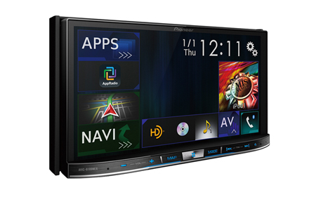
Pioneer AVIC-6100NEX Bypass Radio Parking Brake Bypass NEX Break Override
If you find any conflicting info to bypass your radio please leave a comment with what you found with your AVIC 6100NEX AVIC-6100NEX Pioneer Radio. If you don’t see the audio radio wiring diagram you need comment and we will try to add it ASAP. Thanks for looking!
DO AT YOUR OWN RISK! No parts needed!
1. Ground the light green parking brake wire.
2. Turn the radio on and push the center menu button on the bottom.
3. Hit the AV icon button.
4. Hit the OFF icon from the AV screen.
5. Push and hold your finger on the bottom left of the screen about a half inch up and a half inch in for about 15 seconds or until you see a black box popup that says “Set On”
Here is the info for bypassing the parking brake lockout on the Pioneer AVIC-7100NEX. It will be useful when installing an aftermarket radio, sound stereo system, or other automotive accessories. Make sure to grab the appropriate tools to test all the wires. Please check it over and use it as a GUIDE to help you locate the appropriate wires. Failure to properly test all the wires may lead to vehicle or bodily damage. This schematic is provided free of charge and may not be 100% accurate. All information is provided as-is and accuracy is not guaranteed. This information is provided for informational purposes only and should not be used while driving.
Pioneer AVIC-7100NEX Bypass Radio Parking Brake Bypass NEX Break Override
If you find any conflicting info please leave a comment with what you found with your AVIC 7100NEX AVIC-7100NEX Pioneer Radio. If you don’t see the audio radio wiring diagram you need comment and we will try to add it ASAP. Thanks for looking!
DO AT YOUR OWN RISK! No parts needed!
1. Ground the light green parking brake wire.
2. Turn the radio on and push the center menu button on the bottom.
3. Hit the AV icon button.
4. Hit the OFF icon from the AV screen.
5. Push and hold your finger on the bottom left of the screen about a half inch up and a half inch in for about 15 seconds or until you see a black box popup that says “Set On”
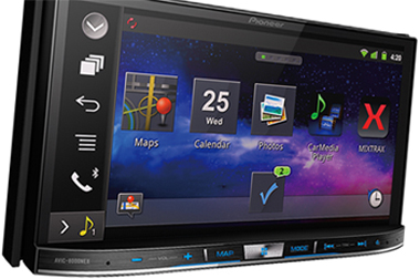
Here is the info for bypassing the parking brake lockout on the Pioneer AVIC-8100NEX. It will be useful when installing an aftermarket radio, sound stereo system, or other automotive accessories. Make sure to grab the appropriate tools to test all the wires. Please check it over and use it as a GUIDE to help you locate the appropriate wires. This schematic is provided free of charge and may not be 100% accurate. Failure to properly test all the wires may lead to vehicle or bodily damage. All information is provided as-is and accuracy is not guaranteed. This information is provided for informational purposes only and should not be used while driving.
Pioneer AVIC-8100NEX Radio Parking Brake Bypass NEX Break Override
If you find any conflicting info please leave a comment with what you found with your AVIC 8100NEX AVIC-8100NEX Pioneer Radio. If you don’t see the audio radio wiring diagram you need comment and we will try to add it ASAP. Thanks for looking!
DO AT YOUR OWN RISK! No parts needed!
1. Ground the light green parking brake wire.
2. Turn the radio on and push the center menu button on the bottom.
3. Hit the AV icon button.
4. Hit the OFF icon from the AV screen.
5. Push and hold your finger on the bottom left of the screen about a half inch up and a half inch in for about 15 seconds or until you see a black box popup that says “Set On”
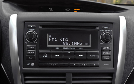
Here is the stereo radio wiring information for your 2012 Subaru Impreza WRX body with the standard or amplified systems. It will be useful when installing an aftermarket radio, sound stereo system, or other automotive accessories. Make sure to grab the appropriate tools to test all the wires in your Impreza WRX. Please check it over and use it as a GUIDE to help you locate the appropriate wires. This schematic is provided free of charge and may not be 100% accurate. Failure to properly test all the wires may lead to vehicle or bodily damage. All information is provided as-is and accuracy is not guaranteed.
2012 Impreza WRX Radio WIring DIagram Install
If you find any conflicting info please leave a comment with what you found in your Subaru Impreza. If you don’t see the audio radio wiring diagram you need comment and we will try to add it ASAP. Thanks for looking!
2012 Subaru Impreza WRX Audio Wiring Radio Diagram Schematic Colors – Aftermarket Stereo Installation Help
Car Radio Constant 12v+ Wire: Blue/Red @ Radio Harness Car Stereo Ground Wire: Black @ Radio Harness Car Radio Ignition Switched Wire: Yellow/Red @ Radio Harness Car Radio Illumination Wire: Purple @ Radio Harness Car Stereo Power Antenna: Yellow/Black @ Radio Harness Car Radio Amp Turn On Wire: N/A
Left Front Speaker Wire (+) Positive: Blue/Orange Left Front Speaker Wire (-) Negative: White/Black Right Front Speaker Wire (+) Positive: Brown/Yellow Right Front Speaker Wire (-) Negative: Green
Left Rear Speaker Wire (+) Positive: White/Red Left Rear Speaker Wire (-) Negative: Red/Black Right Rear Speaker Wire (+) Positive: Gray/Green Right Rear Speaker Wire (-) Negative: Red/White
SPEAKER WIRE COLORS AT THE SPEAKERS IN THE DOORS
Left Front Door Speaker Wire (+) Positive: Left Front Door Speaker Wire (-) Negative:
Right Front Door Speaker Wire (+) Positive: Right Front Door Speaker Wire (-) Negative:
Left Rear Door Speaker Wire (+) Positive: Left Rear Door Speaker Wire (-) Negative:
Right Rear Door Speaker Wire (+) Positive: Right Rear Door Speaker Wire (-) Negative:
Center Channel Speaker Wire Positive / Negative: N/A
Subwoofer Speaker Wire Positive / Negative: N/A
Retain OEM USB In Center Console
This cable will plugin behind the radio and keep your OEM USB functional with a new aftermarket radio:
Retain OEM AUX In Center Console
Take a normal rca cable and cut one end off leaving yourself RCAs and a foot or two of slack. Strip the left and right ends twist the common shields together and then connect them to the following wires:
OEM AUX Left (+) Positive: Yellow – On models with OEM Bluetooth @ White 16 Plug Pin 3 OEM AUX Right (+) Positive: Blue – On models with OEM Bluetooth @ White 16 Plug Pin 4 OEM AUX Common Shield: Black – On models with OEM Bluetooth @ White 16 Plug Pin 11
Radio Size: Single or Double Din
Radio Removal Tools:– Dash Removal Plastic Pry Tools – Use the pry tools to remove the bezel surrounding the radio. After that use a Phillips screwdriver the radio is held in with 4 screws.
Keep in mind if you are installing a new radio in your Impreza you need the wiring harness, the antenna adapter, steering wheel control module, and the mounting kit as well.
Here is the info for bypassing the parking brake lockout on the Pioneer AVIC-6000NEX. It will be useful when installing an aftermarket radio, sound stereo system, or other automotive accessories. Make sure to grab the appropriate tools to test all the wires. Please check it over and use it as a GUIDE to help you locate the appropriate wires. This schematic is provided free of charge and may not be 100% accurate. Failure to properly test all the wires may lead to vehicle or bodily damage. All information is provided as-is and accuracy is not guaranteed. This information is provided for informational purposes only and should not be used while driving.
Pioneer AVIC-6000NEX Radio Parking Brake Bypass Override
If you find any conflicting info please leave a comment with what you found with your AVIC 6000NEX AVIC-6000NEX Pioneer Radio. If you don’t see the audio radio wiring diagram you need comment and we will try to add it ASAP. Thanks for looking!
DO AT YOUR OWN RISK! No parts needed!
1. Ground the light green parking brake wire.
2. Turn the radio on and push the center menu button on the bottom.
3. Hit the AV icon button.
4. Hit the OFF icon from the AV screen.
5. Push and hold your finger on the bottom left of the screen about a half inch up and a half inch in for about 15 seconds or until you see a black box popup that says “Set On”
Here is the info for bypassing the parking brake lockout on the Pioneer AVIC-7000NEX. It will be useful when installing an aftermarket radio, sound stereo system, or other automotive accessories. Make sure to grab the appropriate tools to test all the wires. Please check it over and use it as a GUIDE to help you locate the appropriate wires. This schematic is provided free of charge and may not be 100% accurate. Failure to properly test all the wires may lead to vehicle or bodily damage. All information is provided as-is and accuracy is not guaranteed. This information is provided for informational purposes only and should not be used while driving.
If you find any conflicting info please leave a comment with what you found with your AVIC 7000NEX AVIC-7000NEX Pioneer Radio. If you don’t see the audio radio wiring diagram you need comment and we will try to add it ASAP. Thanks for looking!
DO AT YOUR OWN RISK! No parts needed!
1. Ground the light green parking brake wire.
2. Turn the radio on and push the center menu button on the bottom.
3. Hit the AV icon button.
4. Hit the OFF icon from the AV screen.
5. Push and hold your finger on the bottom left of the screen about a half inch up and a half inch in for about 15 seconds or until you see a black box popup that says “Set On”
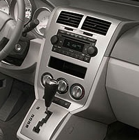
Here is the stereo radio wiring information for your 2009 Dodge Caliber body with the standard or amplified systems. It will be useful when installing an aftermarket radio, sound stereo system, or other automotive accessories. Make sure to grab the appropriate tools to test all the wires in your Caliber. Please check it over and use it as a GUIDE to help you locate the appropriate wires. This schematic is provided free of charge and may not be 100% accurate. Failure to properly test all the wires may lead to vehicle or bodily damage. All information is provided as-is and accuracy is not guaranteed.
2009 Dodge Caliber Audio Radio Wiring Diagram Schematic
If you find any conflicting info please leave a comment with what you found in your Dodge Caliber. If you don’t see the audio radio wiring diagram you need comment and we will try to add it ASAP. Thanks for looking!
2009 Dodge Caliber Audio Wiring Radio Diagram Schematic Colors – Aftermarket Stereo Installation Help
Car Radio Constant 12v+ Wire: Red/Light Blue Car Stereo Ground Wire: Black/Yellow or Black/Green Car Radio Ignition Switched Wire: @ Cigarette Lighter Below Radio Car Radio Illumination Wire: White/Purple @ Drivers kick panel harness Car Stereo Power Antenna: Gray/Red (+) @ Radio Harness Car Radio Amp Turn On Wire:
Left Front Speaker Wire (+) Positive: Gray/Purple Left Front Speaker Wire (-) Negative: Gray/Yellow Right Front Speaker Wire (+) Positive: Green/Purple Right Front Speaker Wire (-) Negative: Green/Yellow
Left Rear Speaker Wire (+) Positive: Green/Dark Blue Left Rear Speaker Wire (-) Negative: Green/Brown Right Rear Speaker Wire (+) Positive: Gray/Dark Blue Right Rear Speaker Wire (-) Negative: Gray/Orange
SPEAKER WIRE COLORS AT THE SPEAKERS IN THE DOORS
Left Front Door Speaker Wire (+) Positive: Left Front Door Speaker Wire (-) Negative:
Right Front Door Speaker Wire (+) Positive: Right Front Door Speaker Wire (-) Negative:
Left Rear Door Speaker Wire (+) Positive: Left Rear Door Speaker Wire (-) Negative:
Right Rear Door Speaker Wire (+) Positive: Right Rear Door Speaker Wire (-) Negative:
Center Channel Speaker Wire Positive / Negative: N/A
Subwoofer Speaker Wire Positive / Negative: N/A
Radio Size: Single or Double Din
Radio Removal Tools:
Keep in mind if you are installing a new radio in your Caliber you need the wiring harness, the antenna adapter, steering wheel control module, and the mounting kit as well.
REQUIRED PARTS FOR AFTERMARKET RADIO INSTALL
BASE SYSTEM WIRING HARNESS:
MOUNTING KIT FOR DOUBLE DIN AFTERMARKET RADIOS:
(This kit can be used with double or single din radios! Vehicle MUST have OEM navigation to use this kit OR you will also need to purchase the OEM Nav Bezel
.
MOUNTING KIT FOR SINGLE DIN AFTERMARKET RADIOS:
(This kit can be used ONLY with single din radios! Vehicle must NOT have OEM navigation.
Use these when replacing the OEM speakers if you don’t want to cut or splice the OEM harness. Comes with 1 pair if doing all 4 speakers you will need to order 2.
RECOMMENDED TOOLS FOR THE INSTALL – SAME ONES THE PROS USE!
Here is the stereo radio wiring information for your 2008 Dodge Caliber body with the standard or amplified systems. It will be useful when installing an aftermarket radio, sound stereo system, or other automotive accessories. Make sure to grab the appropriate tools to test all the wires in your Caliber. Please check it over and use it as a GUIDE to help you locate the appropriate wires. This schematic is provided free of charge and may not be 100% accurate. Failure to properly test all the wires may lead to vehicle or bodily damage. All information is provided as-is and accuracy is not guaranteed.
2008 Dodge Caliber Audio Radio Wiring Diagram Schematic
If you find any conflicting info please leave a comment with what you found in your Dodge Caliber. If you don’t see the audio radio wiring diagram you need comment and we will try to add it ASAP. Thanks for looking!
2008 Dodge Caliber Audio Wiring Radio Diagram Schematic Colors – Aftermarket Installation Help
Car Radio Constant 12v+ Wire: Red/Light Blue Car Stereo Ground Wire: Black/Yellow or Black/Green Car Radio Ignition Switched Wire: @ Cigarette Lighter Below Radio Car Radio Illumination Wire: White/Purple @ Drivers kick panel harness Car Stereo Power Antenna: Gray/Red (+) @ Radio Harness Car Radio Amp Turn On Wire:
Left Front Speaker Wire (+) Positive: Gray/Purple Left Front Speaker Wire (-) Negative: Gray/Yellow Right Front Speaker Wire (+) Positive: Green/Purple Right Front Speaker Wire (-) Negative: Green/Yellow
Left Rear Speaker Wire (+) Positive: Green/Dark Blue Left Rear Speaker Wire (-) Negative: Green/Brown Right Rear Speaker Wire (+) Positive: Gray/Dark Blue Right Rear Speaker Wire (-) Negative: Gray/Orange
SPEAKER WIRE COLORS AT THE SPEAKERS IN THE DOORS
Left Front Door Speaker Wire (+) Positive: Left Front Door Speaker Wire (-) Negative:
Right Front Door Speaker Wire (+) Positive: Right Front Door Speaker Wire (-) Negative:
Left Rear Door Speaker Wire (+) Positive: Left Rear Door Speaker Wire (-) Negative:
Right Rear Door Speaker Wire (+) Positive: Right Rear Door Speaker Wire (-) Negative:
Center Channel Speaker Wire Positive / Negative: N/A
Subwoofer Speaker Wire Positive / Negative: N/A
Radio Size: Single or Double Din
Radio Removal Tools:
Keep in mind if you are installing a new radio you need the wiring harness, the antenna adapter, steering wheel control module, and the mounting kit as well.
REQUIRED PARTS FOR AFTERMARKET RADIO INSTALL
AMPLIFIED SYSTEM WIRING HARNESS:
BASE SYSTEM WIRING HARNESS:
MOUNTING KIT FOR DOUBLE DIN AFTERMARKET RADIOS:
(This kit can be used with double or single din radios! Vehicle MUST have OEM navigation to use this kit OR you will also need to purchase the OEM Nav Bezel
.
MOUNTING KIT FOR SINGLE DIN AFTERMARKET RADIOS:
(This kit can be used ONLY with single din radios! Vehicle must NOT have OEM navigation.
Use these when replacing the OEM speakers if you don’t want to cut or splice the OEM harness. Comes with 1 pair if doing all 4 speakers you will need to order 2.
RECOMMENDED TOOLS FOR THE INSTALL – SAME ONES THE PROS USE!
Here is the stereo radio wiring information for your 2007 Dodge Caliber body with the standard or amplified systems. It will be useful when installing an aftermarket radio, sound stereo system, or other automotive accessories. Make sure to grab the appropriate tools to test all the wires in your Caliber. Please check it over and use it as a GUIDE to help you locate the appropriate wires. This schematic is provided free of charge and may not be 100% accurate. Failure to properly test all the wires may lead to vehicle or bodily damage. All information is provided as-is and accuracy is not guaranteed.
Dodge Caliber Audio Radio Wiring Diagram Schematic
If you find any conflicting info please leave a comment with what you found in your Dodge Caliber. If you don’t see the audio radio wiring diagram you need comment and we will try to add it ASAP. Thanks for looking!
2007 Dodge Caliber Audio Wiring Radio Diagram Schematic Colors
Car Radio Constant 12v+ Wire: Red/Light Blue Car Stereo Ground Wire: Black/Yellow or Black/Green Car Radio Ignition Switched Wire: @ Cigarette Lighter Below Radio Car Radio Illumination Wire: White/Purple @ Drivers kick panel harness Car Stereo Power Antenna: Gray/Red (+) @ Radio Harness Car Radio Amp Turn On Wire:
Left Front Speaker Wire (+) Positive: Gray/Purple Left Front Speaker Wire (-) Negative: Gray/Yellow Right Front Speaker Wire (+) Positive: Green/Purple Right Front Speaker Wire (-) Negative: Green/Yellow
Left Rear Speaker Wire (+) Positive: Green/Dark Blue Left Rear Speaker Wire (-) Negative: Green/Brown Right Rear Speaker Wire (+) Positive: Gray/Dark Blue Right Rear Speaker Wire (-) Negative: Gray/Orange
SPEAKER WIRE COLORS AT THE SPEAKERS IN THE DOORS
Left Front Door Speaker Wire (+) Positive: Left Front Door Speaker Wire (-) Negative: Right Front Door Speaker Wire (+) Positive: Right Front Door Speaker Wire (-) Negative:
Left Rear Door Speaker Wire (+) Positive: Left Rear Door Speaker Wire (-) Negative: Right Rear Door Speaker Wire (+) Positive: Right Rear Door Speaker Wire (-) Negative:
Center Channel Speaker Wire Positive / Negative: N/A
Subwoofer Speaker Wire Positive / Negative: N/A
Radio Size: Single or Double Din
Radio Removal Tools:
Keep in mind if you are installing a new radio you need the wiring harness, the antenna adapter, steering wheel control module, and the mounting kit as well.
REQUIRED PARTS FOR AFTERMARKET RADIO INSTALL
BASE SYSTEM WIRING HARNESS:
AMPLIFIED SYSTEM WIRING HARNESS:
MOUNTING KIT FOR DOUBLE DIN AFTERMARKET RADIOS:
(This kit can be used with double or single din radios! Vehicle MUST have OEM navigation to use this kit OR you will also need to purchase the OEM Nav Bezel
.
MOUNTING KIT FOR SINGLE DIN AFTERMARKET RADIOS:
(This kit can be used ONLY with single din radios! Vehicle must NOT have OEM navigation.
Use these when replacing the OEM speakers if you don’t want to cut or splice the OEM harness. Comes with 1 pair if doing all 4 speakers you will need to order 2.
RECOMMENDED TOOLS FOR THE INSTALL – SAME ONES THE PROS USE!
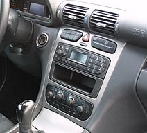
Here is the stereo radio wiring information for your 2002 MB C230 W203 Kompressor body with the standard or amplified systems. It will be useful when installing an aftermarket radio, sound stereo system, or other automotive accessories. Make sure to grab the appropriate tools to test all the wires in your C230. Please check it over and use it as a GUIDE to help you locate the appropriate wires. This schematic is provided free of charge and may not be 100% accurate. Failure to properly test all the wires may lead to vehicle or bodily damage. All information is provided as-is and accuracy is not guaranteed.
2002 Mercedes W203 C230 Audio Wiring Diagram
If you find any conflicting info please leave a comment with what you found in your W203 C230. If you don’t see the audio radio wiring diagram you need comment and we will try to add it ASAP. Thanks for looking!
Car Radio Constant 12v+ Wire: Red/Blue Car Stereo Ground Wire: Brown Car Radio Ignition Switched Wire: Black/Yellow @ Cigarette Lighter Below Radio Car Radio Illumination Wire: Gray/Blue @ Cigarette Lighter Below Radio Car Stereo Power Antenna: Black (+) @ Radio Harness Car Radio Amp Turn On Wire:
Left Front Speaker Wire (+) Positive: Light Green Left Front Speaker Wire (-) Negative: Brown/Light Green Right Front Speaker Wire (+) Positive: Orange Right Front Speaker Wire (-) Negative: Brown/Orange
Left Rear Speaker Wire (+) Positive: Pink Left Rear Speaker Wire (-) Negative: Brown/Pink Right Rear Speaker Wire (+) Positive: White Right Rear Speaker Wire (-) Negative: Brown/White
SPEAKER WIRE COLORS AT THE SPEAKERS IN THE DOORS
Left Front Door Speaker Wire (+) Positive: Left Front Door Speaker Wire (-) Negative: Right Front Door Speaker Wire (+) Positive: Right Front Door Speaker Wire (-) Negative:
Left Rear Door Speaker Wire (+) Positive: Left Rear Door Speaker Wire (-) Negative: Right Rear Door Speaker Wire (+) Positive: Right Rear Door Speaker Wire (-) Negative:
Center Channel Speaker Wire Positive / Negative: N/A
Subwoofer Speaker Wire Positive / Negative: N/A
Radio Size: Single or Double Din
Radio Removal Tools:Plastic Bezel Removal Tools to pop the shifter gear selector trim (don’t completely remove). Then pop the larger shifter bezel and remove that over the smaller one. Use the pick tools to remove the pocket and cigarette lighter bezel. Next use the pick tools to release the spring clips inside the vents and rotate the vents upward to reveal torx screws to remove using this Torx Driver Set. Return the vents to their normal position then use the pick tools to release the spring clips and rotate the vents downward to reveal clips up top to pull down a bit to remove the vent panel. After that remove the torx at the top of radio bezel, and the metal clips at the bottom then unplug and remove that bezel. (don’t turn the vehicle on once you unplug the airbag connector). Finally 4 screws hold the radio in.
Keep in mind if you are installing a new radio you need the wiring harness, the antenna adapter, steering wheel control module, and the mounting kit as well.
REQUIRED PARTS FOR AFTERMARKET RADIO INSTALL
BASE SYSTEM WIRING HARNESS:
MOUNTING KIT FOR DOUBLE DIN AFTERMARKET RADIOS:
(This kit can be used with double din radios only!)